3 jumpers setting and connectors – Aplex Technology ACS-2702 User Manual
Page 13
ACS-2702 User Manual 12
2.3 Jumpers Setting and Connectors
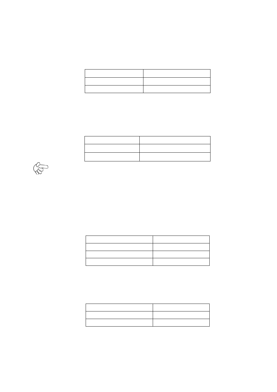
1. JP5:
(2.0mm Pitch 1X2 box Pin Header), ATX Power and Auto Power on jumper setting.
JP5
Mode
Open
ATX Power
Close
Auto Power on (Default)
2. JP3:
(2.0mm Pitch 1X2 Pin Header)CMOS clear jumper, CMOS clear operation will
permanently reset old BIOS settings to factory defaults.
JP3
CMOS
Open
NORMAL (Default)
Close 1-2
Clear CMOS
Procedures of CMOS clear:
a) Turn off the system and unplug the power cord from the power outlet.
b) To clear the CMOS settings, use the jumper cap to close pins 1 and 2 for about 3
seconds then reinstall the jumper clip back to pins open.
c) Power on the system again.
d) When entering the POST screen, press the <F1> or <DEL> key to enter CMOS Setup
Utility to load optimal defaults.
e) After the above operations, save changes and exit BIOS Setup.
Model
JP3
SBC-7106-N2600
No
SBC-7106-N2600-P
No
SBC-7106-D2550
Yes
3. BAT1 :
(1.25mm Pitch 1X2 box Pin Header) 3.0V Li battery is embedded to provide power for
CMOS.
Pin#
Signal Name
Pin1
VBAT
PIN2
Ground
4. DC_IN1:
(5.08mm Pitch 1x3 Pin Connector),DC9V~32V System power input connector。