Instructions – Basler Electric BE3-74TD User Manual
Page 2
vibration-free location where the ambient temperature does
not exceed the operating temperature range. Connections to
the relay should be made using wire that meets applicable
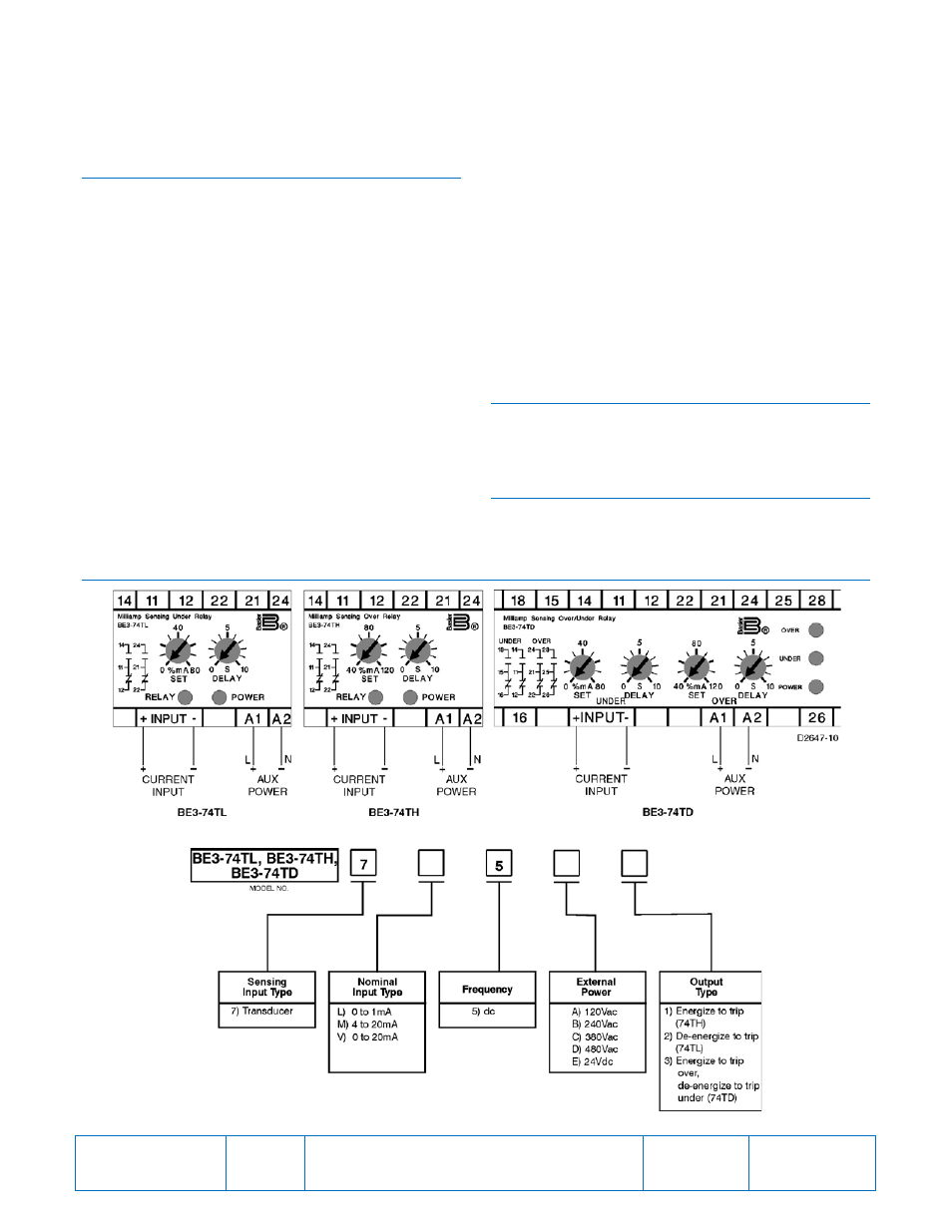
codes and is properly sized for the application. Figure 1
shows the input connections for the BE3-74TD, BE3-74TH,
and BE3-74TL relays.
CALIBRATION
The calibration marks on the faceplate have a maximum
error of 10% and are provided only as guides. Proper
calibration requires inserting an accurate milliammeter in
series with the input signal. Use the following procedure to
calibrate your relay.
Overcurrent Trip
1.
Adjust the SET control fully clockwise and the DELAY
control fully counterclockwise. Apply nominal external
operating power to the relay.
2.
Apply the desired trip current to the relay.
3.
Slowly adjust the SET control counterclockwise until the
relay trips.
Overcurrent Delay
1.
Set the DELAY control at the desired time setting. Apply
nominal external operating power to the relay.
2.
Apply a value of current that is just above the trip
setpoint. Measure the time from when the current is
applied until the relay trips.
3.
Compare the measured time to the desired time delay
and adjust the DELAY control accordingly.
4.
Repeat Steps 2 and 3 as required.
Undercurrent Trip
1.
Adjust the SET control and DELAY control fully
counterclockwise. Apply nominal external operating
power to the relay.
2.
Apply the desired trip current to the relay.
3.
Slowly adjust the SET control clockwise until the relay
trips.
Undercurrent Delay
1.
Set the DELAY control at the desired time setting. Apply
nominal external operating power to the relay.
2.
Apply a value of current that is above the trip setpoint.
Remove the applied current. Measure the time from
when the current is removed until the relay trips.
3.
Compare the measured time to the desired time delay
and adjust the DELAY control accordingly.
4.
Repeat Steps 2 and 3 as required.
MAINTENANCE
BE3 relays are solid-state devices that require no
maintenance. In the event that your relay requires repair,
contact Basler Electric, Highland, IL, USA for return
authorization.
ORDERING INFORMATION
Figure 2 shows the BE3 milliamp sensing alarm relay style
number identification chart.
FIGURES
Figure 1. BE3-74TD, BE3-74TH, and BE-74TL Input Connections
Figure 2. BE3-74TD, BE3-74TH, and BE3-74TL Style Number Identification Chart
Publication
9321100990
Revision
C
Instructions
Date
04/14
Page
2 of 2