Controls and indicators, Introduction, Section 2 – Basler Electric BE1-59NC User Manual
Page 17: Controls and indicators -1
SECTION 2
• CONTROLS AND INDICATORS
INTRODUCTION
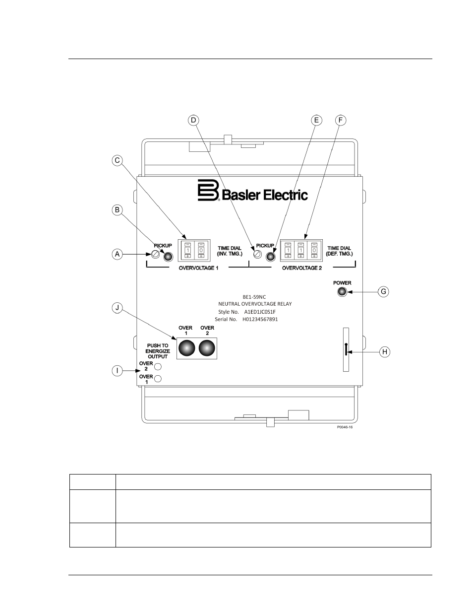
Controls and indicators are located on the front panel. The controls and indicators are shown in Figure
2-1 and described in Table 2-1. Figure 2-1 illustrates a relay with the maximum number of controls and
indicators. Your relay may not have all of the controls and indicators shown and described here.
Figure 2-1. Location of Controls and Indicators
Table 2-1. Control and Indicator Descriptions
Locator
Description
A
OVERVOLTAGE 1 PICKUP Adjustment. A multiturn potentiometer that sets the
overvoltage comparator threshold voltage. Continuously adjustable for the sensing input
voltage range.
B
OVERVOLTAGE 1 PICKUP LED. A red LED that illuminates when overvoltage exceeds
the pickup setting.
9279400990 Rev D
BE1-59NC Controls and Indicators
2-1