BECKHOFF CX1100-000x User Manual
Page 50
Error handling and diagnostics
48
Embedded PC
5. Error handling and diagnostics
Terminal Bus Analysis in PLC-Program
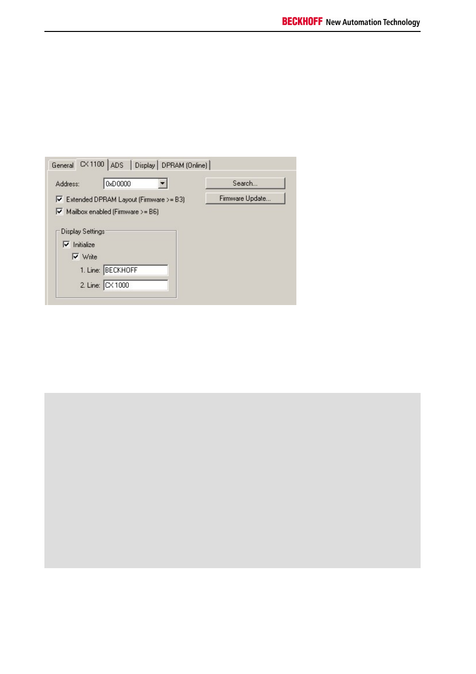
To analyze the terminal bus (K-Bus and IP-Link) the programmer can access the registers described in the
architecture. The access to the PLC-program is realzed via TwinCAT. To have the access to the necessary registers
the extended DPRAM model has to be activated (only in Firmware > B3). The registers are described in the
architecture of the terminal bus connectors.
Though the handling is identical for both sub busses the explaination is done generally.
For analysis four signals / variables are used:
BusState (describes the state of the bus: 0 -> no error, 1 -> bus error)
ErrorCode (same error code as the LED blink code)
ErrorArg (same argument code LED blink code)
Request[0] (output to request error codes / reset bus)
In the PLC program some external variables must be defined:
VAR
k_bus_request AT %QX0.0
: BOOL;
k_bus_err_code AT %IB0
: USINT;
k_bus_err_arg AT %IB1
: USINT;
k_bus_state AT %IB2
: USINT;
ip_bus_request AT %QX0.1 : BOOL;
ip_bus_err_code AT %IB3
: USINT;
ip_bus_err_arg AT %IB4
: USINT;
ip_bus_state AT %IB5
: USINT;
END_VAR
In the PLC program the analysis can be done as follows: (this is only pseudo code)