Description of functions, Terminal configuration – BECKHOFF KL6051 User Manual
Page 6
Description of functions
6
KL6051
Description of functions
The KL6051 serial interface terminal enables an exchange of data between
different field bus systems. Regardless of the higher-level field bus system,
data can be exchanged in full duplex mode. Up to 40 inputs and 40 outputs
are transmitted between the field bus systems and, in addition, the status
byte contains information about the quality and the status of data transfer.
The terminal is supplied with a 200 ms RCV timeout, i.e. the inputs of the
higher-level controller are set to zero if the terminal does not receive any
valid data via the serial interface from the second station within 200 ms. In
the default setting, 32 bits are bidirectionally available for data exchange.
Features
Coupling of two field bus systems
Exchange of up to 40 bits bidirectionally
Status byte for data channel status message
Safeguarded data transfer by longitudinal parity, vertical parity, log
Transmission medium: RS422 full duplex
Maximum transmission distance: 1000 m
Simple software interface for control by the emulation of up to 40 bits
Parallel I/O
Data transfer time exchange time < 5 ms
Terminal configuration
The terminal can be configured and parametrized via the internal register
structure.
Each terminal channel is mapped in the bus coupler. The data of the termi-
nal is mapped differently in the memory of the bus coupler depending on
the type of the bus coupler and on the set mapping configuration (eg Moto-
rola / Intel format, word alignment.
For parametrization of a terminal, the control / status byte must also be
mapped.
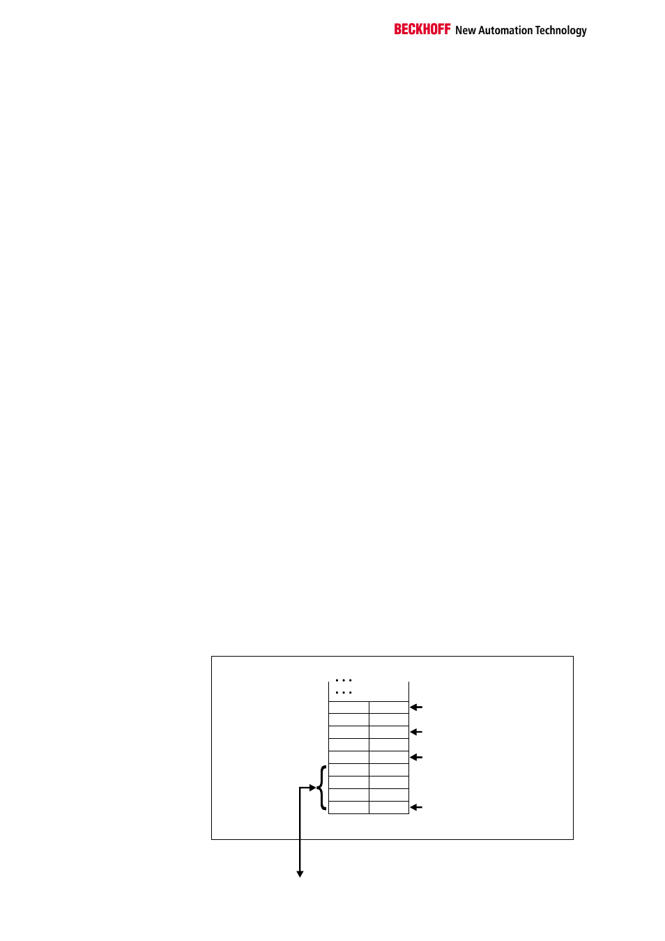
Beckhoff Lightbus
coupler BK2000
When using the Beckhoff Lightbus coupler BK2000, the control / status
byte is always mapped in additon to the data bytes. It is always in the low
byte at the offset address of the terminal channel. In the case of the
KL6051 there will be 6 bytes data (5 bytes user data and 1 byte con-
trol/status) exchanged with the control system.
0
Offset Terminal1 = 0
KL6051
Offset Terminal2 Channel1 = 1
Offset Terminal2 Channel2 = 2
Offset Terminal3 Channel1 = 1
User information data allocation
depending on mapping
K-Bus
Beckhoff Lightbus
bus coupler
BK2000
To the bus terminal
L
H
C/S
D0
D1
D2
D3
Data L
Data L
Data H
Data H
D4
C/S
C/S
C/S
The terminal is
mapped in the
bus coupler