Electrical connection (example) – BECKHOFF AX5021 User Manual
Page 5
BECKHOFF
Drive Technology
Brake module AX5021 – Version: 1.2
Page 5/8
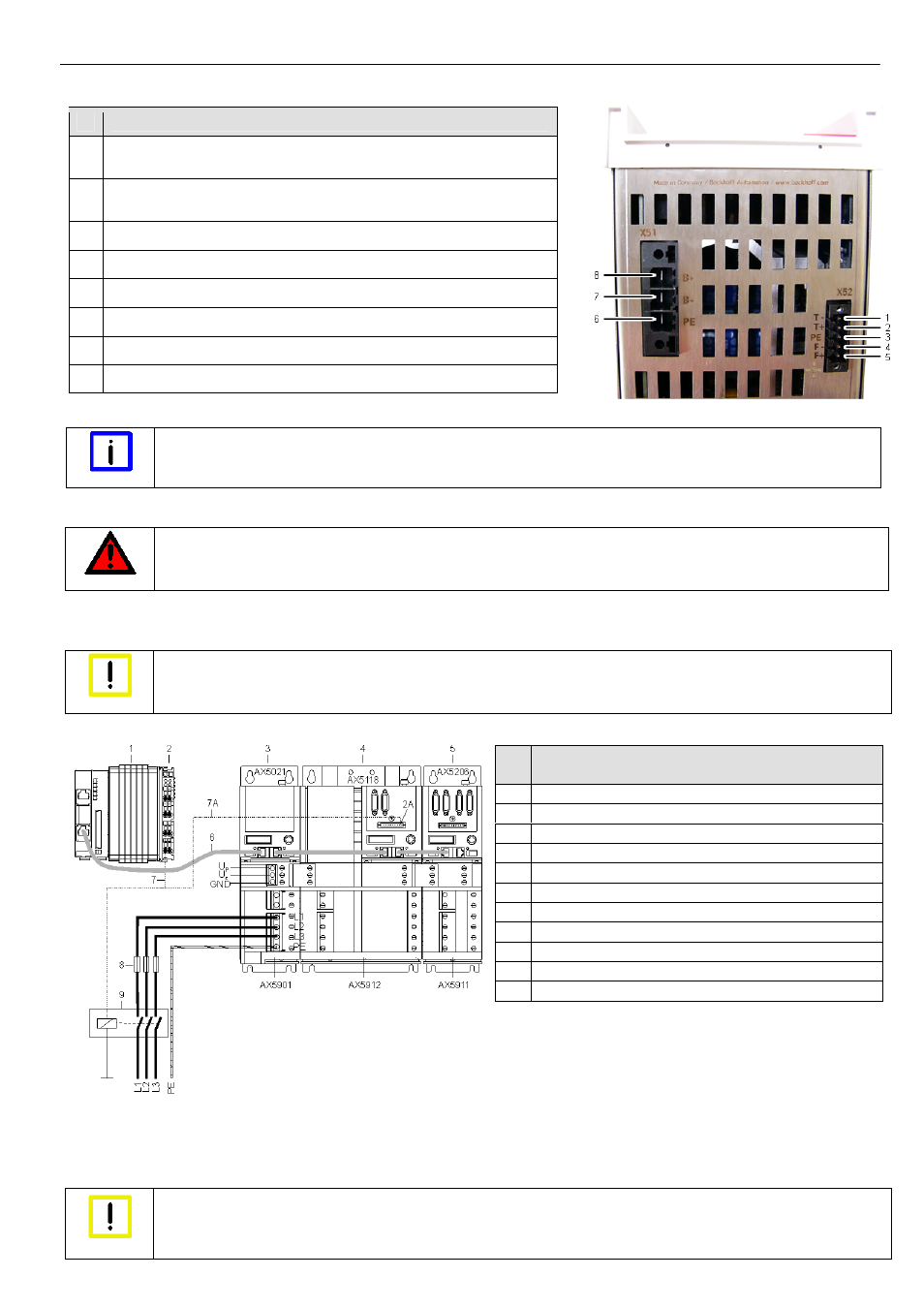
Pin strip assignment of X51 and X52
No
Designation
1
T- = input of the temperature measurement sensor of the external brake
resistor
2
T+ = input of the temperature measurement sensor of the external brake
resistor
3
PE = protective conductor
4
F- = output to the fan controller of the external brake resistor
5
F+ = output to the fan controller of the external brake resistor
6
PE = protective conductor
7
B- = output to the controller of the external brake resistor
8
B+ = output to the controller of the external brake resistor
Please refer to the servo drive ‘Startup’ manual for the pin assignments of the remaining inputs and outputs.
Note
Temperature rise in an external brake resistor
The temperature rise of the external brake resistor should be monitored continuously via temperature contacts (1) and (2).
Electrical connection (example)
DANGER
Caution – Danger of death!
Even when the AX5021 is disconnected from the mains voltage, dangerous voltage continues to be present at the "X02" terminals
of the DC link for 5 minutes. Never touch the terminals within this period.
The example below describes the brake module and several servo drives, which are linked via AX-Bridge modules to make up a drive system. We
recommend that the brake module be placed in the first position with the AX-Bridge power supply module (AX5901) and after that the servo drives
with decreasing rated current; we assume here that the most powerful servo drive also releases the greatest brake energy.
Caution
Hazard to devices
Please analyse your application. The brake module should always be placed directly beside the servo drive that releases the
greatest brake energy. This rule should also be applied if several brake modules are used in a drive system.
Due to the characteristic of the brake module, a mains failure is recognised immediately; hence, it is necessary that you monitor the ready status of
the brake module and disconnect the entire drive system from the mains if necessary. Cyclically check bit 4 – ‘ext. Umain relay’ – in the ‘power
management status word’ (IDN P-0-0205) in the controller. If its value is ‘0’, you must ensure that the mains contactor (9) trips, thus disconnecting
the complete drive system from the mains. For this, you can use a separate output terminal (2) or a free output ‘8’ of the digital I/O s (2A) of a servo
drive.
Caution
Uncontrolled movements
If the drive system is disconnected from the mains due to a mains failure, all axes of the drive system make uncontrolled
movements. Take suitable measures to ensure than no persons are endangered during this time. Vertical axes are particularly
dangerous.
Pos.
Designation
1
PC with TwinCAT and PLC
2 Output
terminal
2A
Output ‘8’ of the servo drive digital I/Os
3 Brake
module
4
Servo drive (with the greatest brake energy)
5 Servo
drive
6 Patch
cable
7
Control cable from the output terminal
7A
Control cable from output ‘8’ of the servo drive digital I/Os
8 Mains
fuses
9 Mains
contactor