Inductive loads – leading edge phase control – BECKHOFF DK9222-0310-0010 User Manual
Page 2
I/O
Bus Terminals
Application Note DK9222-0310-0010
mode of the dimmer is unimportant because of the purely ohmic load. For all illuminants that are connected via electronic
ballasts (EBs), such as low-voltage halogen spots, the construction of the transformer is decisive for the applied control
principle. It should also be noted that mixed loads are not controlled: an ohmic load cannot be controlled together with an
inductive load in a the same circuit, even if the dimmer is suitable for both load types. The dimmer type and the type of the
connectable loads are identifiable by pictograms.
R, L, C
R, L, C
R
L
C
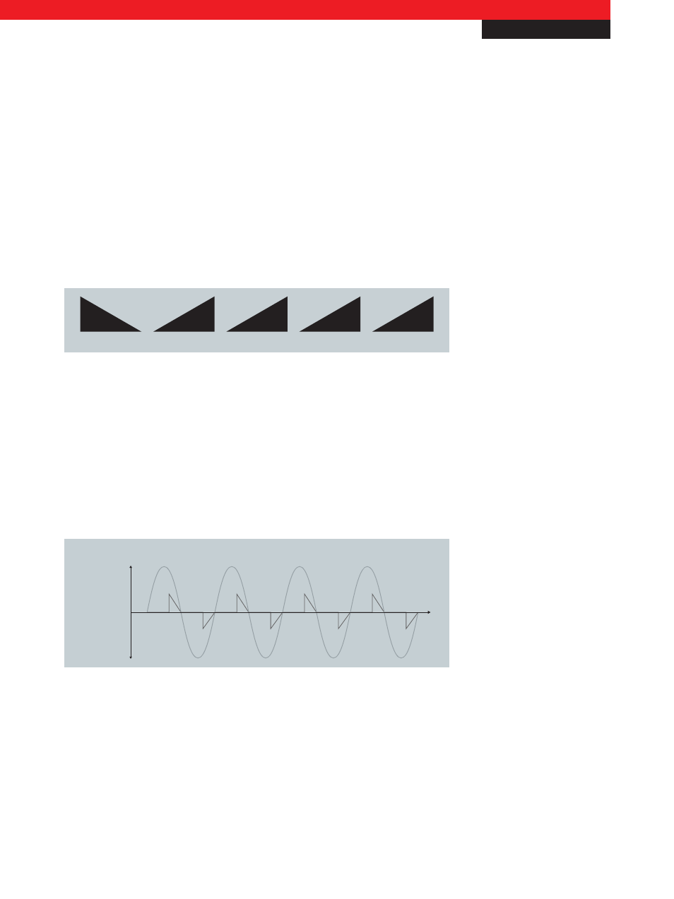
Fig. 1 Meaning of the pictograms: R = ohmic, L = inductive, C = capacitive, descending triangle = leading edge phase control,
ascending triangle = trailing edge phase control
Inductive loads – leading edge phase control
Low-voltage halogen lamps with conventional, inductive (= wire-wound) transformers are controlled by thyristor dimmers
based on leading edge phase control. In the leading edge phase control technique, the switch-on point of the switch is changed
in relation to the mains voltage half-wave. The thyristor thereby becomes conductive at a controllable point within the voltage
half-waves; the flow of current is automatically interrupted at the next zero crossing of the sine half-wave. This ensures that no
inductive voltage peak occurs when switching off.
t
u
i
Leading edge phase control
Voltage u,
Current i
Fig. 2 Change of switch-on point with leading edge phase control
Capacitive and ohmic loads – trailing edge phase control
Trailing edge phase control is used with electronic low-voltage transformers. In the trailing edge phase control technique, the
switch-off point of the switch is changed in relation to the mains voltage half-wave. The current begins to flow exactly at the
zero crossing of the voltage wave; the transistor dimmer terminates the flow of current at a controllable point within the half-
wave. Advantages of this circuit: the flow of current can be interrupted at any time; very accurate control is possible and the
flow of current is also interrupted immediately in the case of an overload or a short-circuit. The generation of current peaks on
input capacitors of the EBs is avoided, since the flat rise of the sine wave is used in order to charge the capacitor. The voltage
New Automation Technology
Beckhoff
2
For application notes see disclaimer on the last page