0 setup, 1 mounting, 2 cabling and connectors – Broadata Communications Mini-HDMI-WP Series User Manual
Page 5
BCI Mini-HDMI-WP User’s Manual
Wall Plate Miniature Multimode Fiber Optic HDMI Transmission System
Broadata Technical Support, (800) 214-0222
6
2.0 SETUP
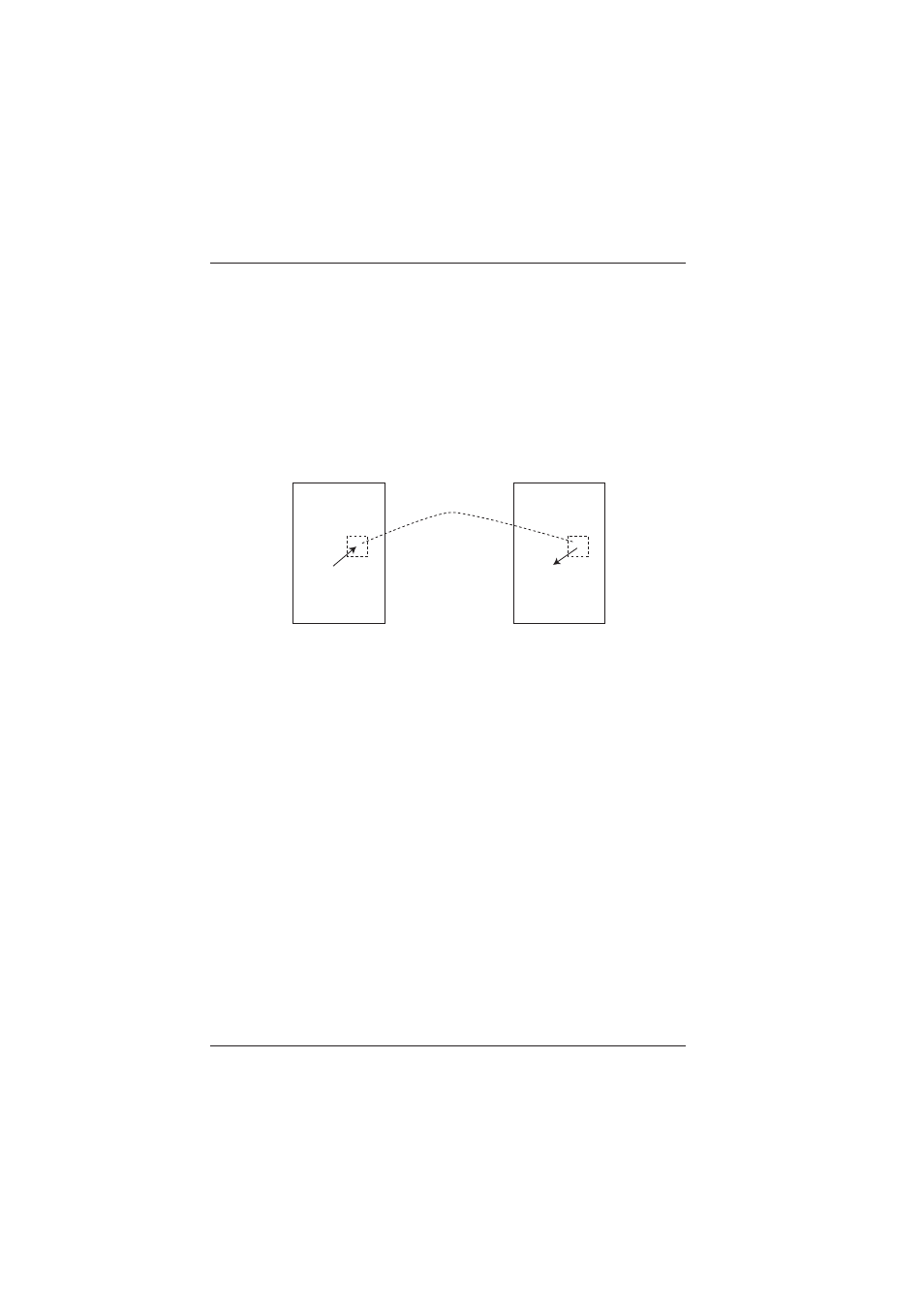
The BCI Mini-HDMI-WP Series units are used in pairs. One
Mini-HDMI-WP-T transmitter unit is located at the near-end and
connected through one optical fiber, to the Mini-HDMI-WP-R receiver
located at the far-end of the link. Figure 2-1 depicts a typical installation
for the Mini-HDMI-WP-T/R.
Figure 2-1
Mini-HDMI-WP Setup
2.1 Mounting
Before installing the units into your wall plate housing, make
sure there is enough space to pull and connect both the electrical
and optical cables without stressing them beyond the
manufacturer’s limitations (also known as the minimum bend
radius).
2.2 Cabling and Connectors
In order to setup the BCI Mini-HDMI-WP properly, make sure to
observe the following instructions when installing the proper
cables. The Mini-HDMI-WP requires two parts to the cabling
setup, the electrical and the optical.
Media Room Wall
Mini-HDMI-T-WP
HDMI Input
(with DDC)
Video Projector Room
Mini-HDMI-R-WP
HDMI Output
(with DDC)
1 Multimode
Fiber