Control inputs, Wire mode, Logic outputs – BSS Audio BLU-50 Install Guide User Manual
Page 14
8
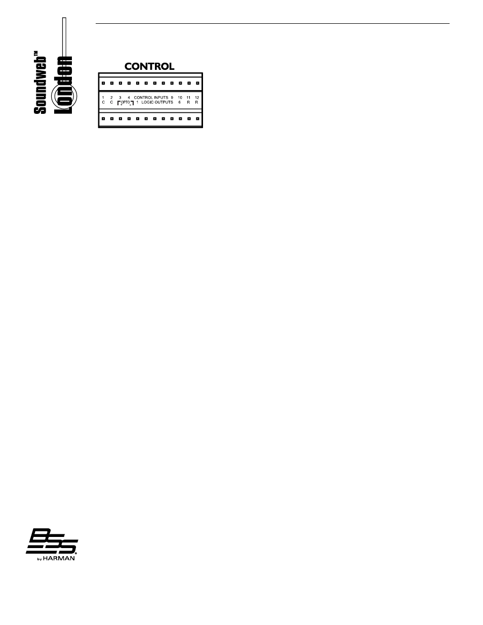
Control Inputs
Used to connect switches or potentiometers, e�g� BLU-3 selector wallplate (Part no� Z-BLU-3)� Looking at the
control port connector (on the back of the unit), there are two common (ground) connections C to the left of the
twelve CONTROL INPUTS and, two software assignable reference voltage outputs R to the right�
The control ports have two modes of operation: 2-wire and 3-wire�
2-Wire Mode
In this mode the twelve CONTROL INPUTS are internally ‘pulled up’ to +5V DC via a 4�7kOhm resistor� Therefore,
no external voltage source is needed to create contact closure to ground for switches such as mute buttons or,
resistance to ground (for other multi-state or continuous controls such as Parameter Presets or faders)�
See the help file within HiQnet London Architect for a table of resistor values for use with Parameter Presets or
source selectors�
Two ‘common’ ground connections are provided using the two C connectors to the left of the CONTROL INPUTS�
A 47kOhm-log potentiometer (Part no� DM10018) connected between a control input and common will allow
parameters to be controlled linearly�
3-Wire Mode
This mode allows the use of linear pots or faders for continuous controls� A pot would be wired as a potential
divider with the top of the track connected to the reference output R, the wiper to a control input and the bottom
of the track to a common C� For good performance, pots with track resistance between 10K and 100KOhms are
recommended�
Logic Outputs
Used to connect ‘tally’ indicator LED’s or relays�
There are six standard LOGIC OUTPUTS which produce 0V or +5V DC via an internal 440 Ohm resistor and two
internally connected common (ground) connections C�
An LED connected between one output (Anode, A) and common (Cathode, K) will illuminate when the LOGIC
OUTPUT is activated, without requiring any external current limiting resistor�
A high sensitivity relay (such as a reed relay) may be driven by connecting four outputs in parallel� This arrangement
will develop 4V across a 500-Ohm coil, providing that all four outputs are made logic 1 simultaneously�