Setup and operation, cont'd – BUG-O Systems CWP-7 User Manual
Page 6
6
SETUP AND OPERATION, CONT'D.
ADDITIONAL CABLES
The circle welders are supplied with the following cables:
1. CWO-3139 50' (15 m) power cable that connects the power source to the cable connector on the
top gear of the machine.
2. CWO-3040 50' (15 m) weld cable that connects the lead coming out of the top of the machine using
the quick connect connector to your power supply.
3. CWO-9406 50' (15 m) gas shielding hose that connects the gas fitting on the top of the shaft to your
shielding gas supply.
WHEEL ADJUSTMENT
The CWP-7 Racking System CWO-1665 and the Large Vertical Racker
CWO-1690 are equipped with adjustable wheels. Always check these
components for proper wheel adjustment before using the machine. The
wheels need adjustment if you can cock or wiggle the components out of
alignment. The wheels should be snug but not prohibit movement along the
path of travel. The wheels with the hex stand offs are adjustable. To adjust
the wheels, loosen the hex bolt
(A) until the adjustable bushing (B) can be
rotated. Correct the wheel alignment by rotating the adjustable bushing
(B).
Once adjusted, hold the adjustable bushing
(B) while tightening the hex bolt
(A). Recheck alignment.
A
B
MACHINE CONTROLS
Please refer to pages 8-9 in this manual entitled CWP-1570 Control Panel for descriptions of the various
control parameters that are available.
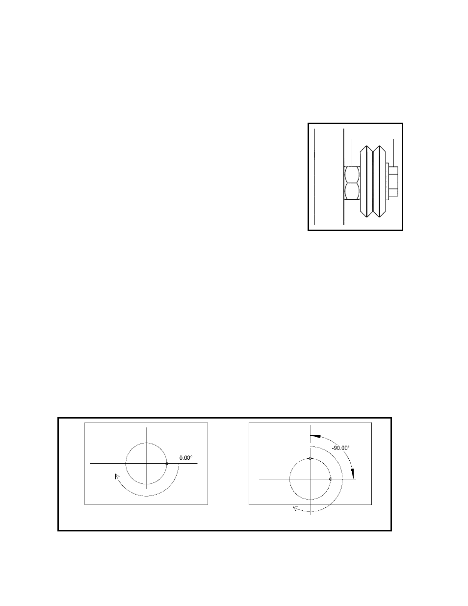
WELD STARTING POSITION
Proper positioning of the electrode is crucial to a successful weld. The CWP-7 rotates in a clockwise
direction. Depending on the job, whether on-center or hillside, or the process, the optimum starting point
of the weld may vary. The desired starting position should be entered at setup as an angle to the pipe
axis direction, as shown in Figure 3.
The default start position (start angle = 0.00°) is shown as A and B in Figure 3. For an on-center joint, this
would be the topmost point. For a hillside joint, -90.00° is the topmost point (C in Figure 3) and 90.00° is
the lowest point.
During setup, enter the Start Angle in hundredths of degrees: 4500 is 45.00°. The machine makes one
revolution from the start point for each pass. Overlap is only added to the last pass.
Figure 3: Weld Start Position for On-center (left) and Offset or Hillside (right) nozzles.
C
B
A