Cw-5 circle welder / wiring diagram, Electrical component chart – BUG-O Systems CW-5 User Manual
Page 12
Advertising
12
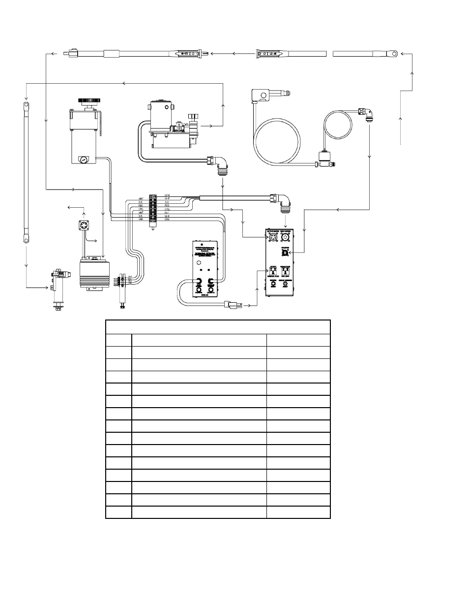
CW-5 CIRCLE WELDER / WIRING DIAGRAM
IN FROM
WELDER
SUPPLY
UNIT
TO POWER
CABLE
1
3
14
11
6
12
8
2
5
4
9
10
13
7
ELECTRICAL COMPONENT CHART
ITEM DESCRIPTION
PART NO.
1
Weld Cable Inlet 2/0
CWO-3020-2/0
2
Weld Cable
CWO-3013
3
Weld Cable 50'
CWO-3019
4
Large Brush Holder & Support
CWO-3059
5
Power Cable
CWO-3139*
6
GMA Pigtail
CWO-3331
7
GMA Wire Feeder Control
CWO-3332
8
P.M. Motor Assembly
CWO-3384
9
CW-5 Collector
CWO-3456
10
Small Brush Retainer Assembly
CWO-3462
11
LN-7 Wire Feeder Assembly
CWO-3468
12
Terminal Block
CWO-3935
13
Rotation Control Box
CWO-6210
14
Solenoid Adapter Kit
CWO-8056
*CWO-3139 Universal CWO-3139-M For Miller Welders
Advertising