6 .........operating instructions / setup, 6 .........go-fer iii-wd / setup (welding), Operating instructions / setup – BUG-O Systems GO-FER III-OX User Manual
Page 6: Go-fer iii-wd / setup (welding)
6
TRACK SETUP
Attach two
ARM-2010 “ON-OFF” Magnet Plate Assemblies (M) one quarter of the length from each
end of the track. The magnets hold the rail to a steel workpiece and give all position capability. Mount
the
ARM-2015 Spacer Bar Assemblies (N) between the Magnet Plate Assemblies (M) to provide
additional rail support. Verify the workpiece is clean and free of contaminants such as rust and oil to
insure maximum magnet holding power. The
ARR-1080 and ARR-1085 Rails (L) are supplied with a
positive rail joining system that enables the user to construct a rail system of any length.
POSITIONING AND ADJUSTING THE MACHINE ON THE TRACK
Disengage the clutch by centering the clutch
Knob (A) over the hole in the cover and pulling the knob
out. This disengages the drive pinion. Slide the carriage wheels into the track V-grooves from the end of
the track. The carriage will move smoothly along the track if the wheels are properly aligned.
The
GO-FER III wheels are factory adjusted to fit ARR-1080 rails. Wheel adjustment should be verified
on older machines. Grasp the carriage sides. The wheels are too loose if the carriage can be moved from
side to side. Use a finger to keep one of the wheels from rotating while manually pushing the carriage
along the track. The wheels are adjusted too tight if firm finger pressure is not
enough to prevent wheel rotation.
WHEEL ADJUSTMENT
The wheels along one side of the carriage have
Stainless Shim Washers
(C) underneath. These wheels (E) are adjustable. Readjust these wheels (if
necessary) by rotating the
Hex Bolt (B) with a 1/2" (13 mm) wrench.
Gently push the clutch
Knob (A) back into the case while gently rocking the
machine forward and backward. This will engage the drive pinion. The rocking
motion is necessary to insure proper gear mesh.
OPERATING INSTRUCTIONS / SETUP
TORCH SET-UP
Insert the
Racking Group (P) into the torch
holder on the rack. Attach the rod, the clamp
and the gun to the end of the vertical tube
rack. Clamp welding gun into gun clamp.
Adjust the racking system to set the gun to
the desired position. Support the gun cable
in the
Cable Anchor (J) provided. The
cable anchor acts as a strain relief to keep
the supply cable from dragging the gun out
of position. Connect the contactor circuit
by crimping the two female connectors
(supplied) to a 22-18 gauge, two-conductor
cable from the trigger circuit of the feeder
and plug them into the two leads on the plug
of the
Contactor Control Box (K).
MACHINE OPERATION
Set
Switch (D) to the center “STOP”
position. Plug in the power cord. Verify the
Pilot Light (F) comes on. Set Switch (D)
to the forward or reverse position to begin
forward or reverse travel. Adjust the travel
speed using the
Speed Control (G).
The
Circuit Breaker (H) protects the
unit against overload or electrical faults.
CAUTION: IF THE CIRCUIT BREAKER
OPENS, FIND AND CORRECT THE
CAUSE BEFORE RESETTING.
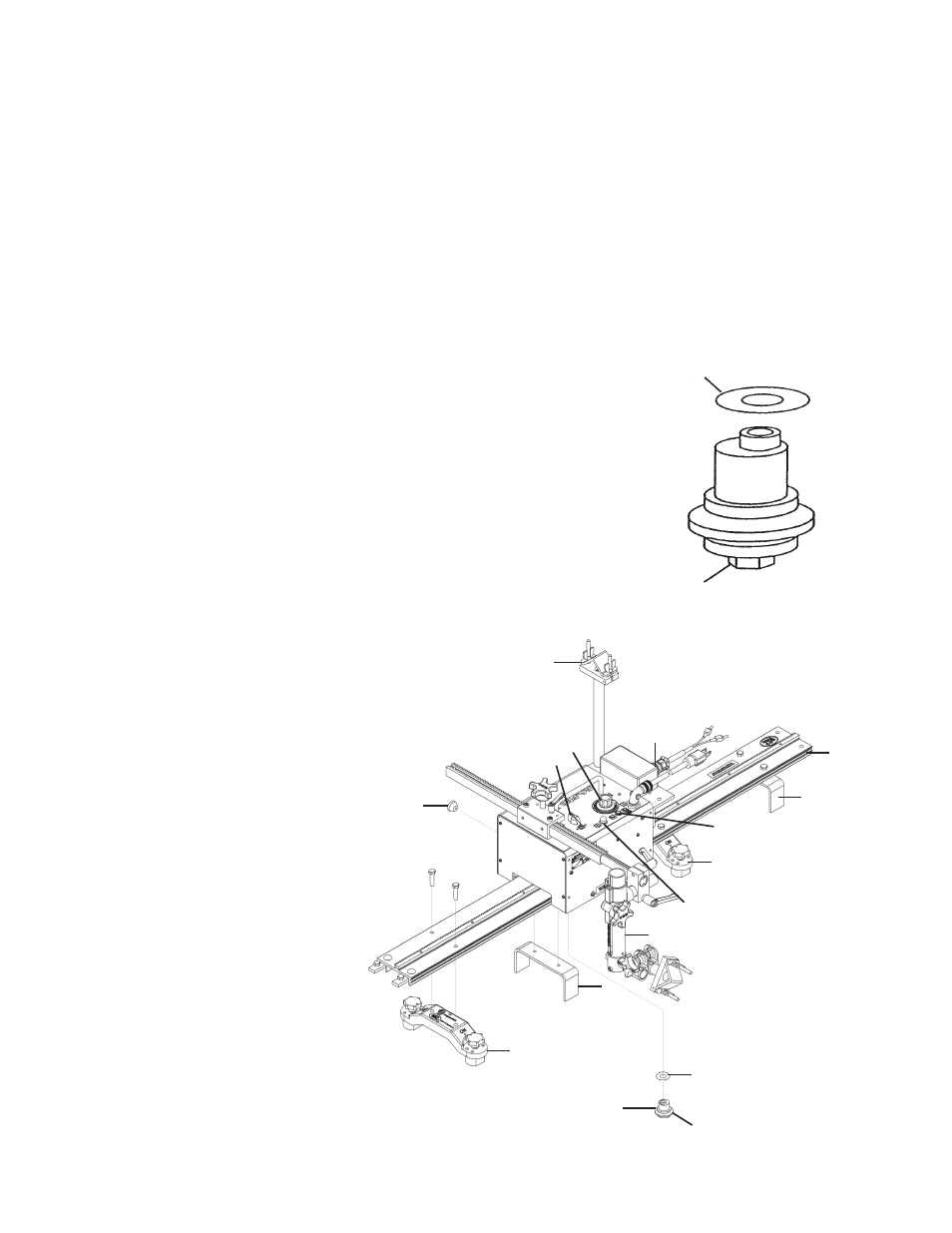
GO-FER III-WD / SETUP (Welding)
D
G
F
H
J
A
M
N
C
B
P
L
N
K
M
C
B
E