Instructions for the installer, Technical specifications table, Maintenance – Caple C981G User Manual
Page 11
11
INSTRUCTIONS FOR THE INSTALLER
MAINTENANCE
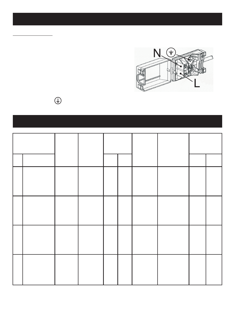
Replacing the power supply cable
Should it be necessary to replace the power supply
cable, use a standard type H05VV-F or H05RR-F cable
with a section of 3 x 0.75 mm
2
.
The connection to the terminal board must be carried
out as shown in the figure on the right:
Brown wire L
(live)
Blue wire N
(neutral)
Green-yellow wire
(earth)
TECHNICAL SPECIFICATIONS TABLE
BURNERS
GAS
WORKING
PRESSURE
HEAT INPUT
NOZZLE
DIAMETER
REGULATORS BY-
PASS DIAMETER
HEAT INPUT
(W)
N°
DESIGNATION
mbar
g/h
L/h
1/100 mm
1/100 mm
Max.
Min.
1
RAPID
G30
28-30
218
-
87
42
3000
950
G31
37
214
-
87
42
3000
950
G20
20
-
286
129
Reg.
3000
950
G25
25
-
332
132
Reg.
3000
950
2
SEMI-RAPID
G30
28-30
120
-
65
31
1650
600
G31
37
118
-
65
31
1650
600
G20
20
-
157
97
Reg.
1650
600
G25
25
-
183
100
Reg.
1650
600
3
AUXILIARY
G30
28-30
73
-
50
27
1000
450
G31
37
71
-
50
27
1000
450
G20
20
-
95
77
Reg.
1000
450
G25
25
-
111
80
Reg.
1000
450
4
TRIPLE CROWN
G30
28-30
255
-
46 / 65
60
4000
2100
G31
37
250
-
46 / 65
60
4000
2100
G20
20
-
334
71 / 95
Reg.
4000
2100
G25
25
-
443
71 / 100
Reg.
4000
2100