Cloud Electronics CXM Mixer User Manual
Page 11
CXM Technical
MANUAL
10
3.16
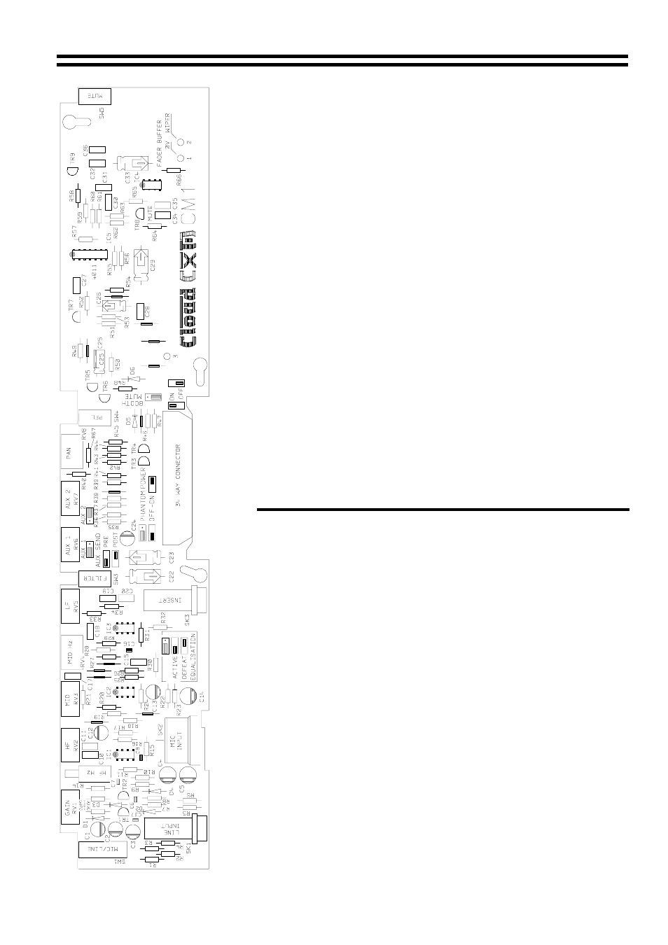
PCB Jumpers
The locations of the PCB configuration jumpers can be seen on the
diagram to the left. The list below explains each jumper, its
approximate position and default settings.
Equalisation jumper, located next to the insert jack socket, factory
set in the active position. 2 possible settings; EQ active or
defeated. No output will be possible from this channel if this jumper
header is missing.
Auxiliary Send 1 Pre / Post Fade, located behind the Aux 1
potentiometer, factory set to Pre Fade. 2 possible settings, Pre or
Post Fade level. Aux Send 1 will not function if this jumper header
is missing.
Auxiliary Send 2 Pre / Post Fade, located behind the Aux 2
potentiometer, factory set to Post Fade. 2 possible settings, Pre or
Post Fade level. Aux Send 2 will not function if this jumper header
is missing.
Phantom Power jumper, located above the 34 way buss connector,
factory set to the Off position. If this jumper header is missing then
+48 Volts phantom power will be Off.
Booth Mute/AutoMute jumper, located to the side of the 34 way
buss connector, factory set to the Off position. If this jumper header
is missing then Booth Mute will never function on this channel.