Options and additional information, Lm-1 and dm-1 active input plates – general, Considerations – Cloud Electronics Z4ii User Manual
Page 18: Connecting multiple dm-1s, Installation and user manual v1.0 18
Z4
II
& Z8
II
Installation and User Manual v1.0
18
LM-1 and DM-1 active input
plates – general considerations
Cloud DM-1 and LM-1 remote input plates are the same
physical size as a double-gang UK electrical socket and can
be mounted in the recessed back box provided or in a
standard surface-mounting box of 35 mm depth.
The modules should be connected to the facility input
of the relevant zone using multi-core screened cable as
described at page 12 (Connecting a DM-1 remote input plate
and Connecting an LM-1 remote input plate). The module
terminations are conventional screw terminals and the
Facility Port on the mixer is a 9-pin Dsub type connector. A
suitable mating connector is provided.
Great care must be taken when terminating the active input
plates; power is derived from the mixer and wiring errors
may cause failure of the mixer. Please check all wiring before
testing the system.
IMPORTANT: Please refer to page 25 (PSU capability and
optional device current consumption)
for information regarding
current draw and power supply capability.
Connecting multiple DM-1s
It may be desirable to connect local microphones at more
than one location in a zone (in a large function room, for
example). DM-1 dual microphone input plates may be “daisy-
chained” to achieve this. All DM-1s thus wired will, of course,
only be available to the zone to whose Facility Port the chain
is connected.
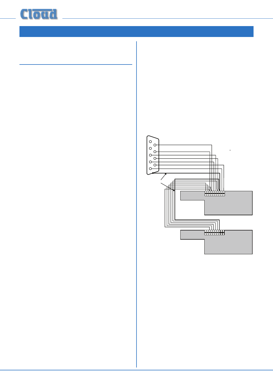
Multiple DM-1s are wired as shown in fig.23. Six
interconnections are used, including a cable screen; it will
generally be convenient to use the same cable type as that
between the mixer and the first DM-1 in the chain, the extra
cores being ignored.
1
9
8
7
6
5
4
3
2
First DM-1 - (uppermost PCB)
1
9 8 7 6 5 4 3 2
10
CABLE SCREEN
Z4
II
/Z8
II
FACILITY PORT
Second DM-1 - (uppermost PCB)
1
9 8 7 6 5 4 3 2
10
fig.23: Connecting multiple DM-1plates
Remember to consider the current drawn by any additional
input plates – see page 25 for details of current consumption
and PSU capability.
Options and Additional Information