Electrical connection – Coloronix SCC5 User Manual
Page 5
Page 5—SCC5-IR-DMX / SCC5-RM-DMX Manual V.1.1
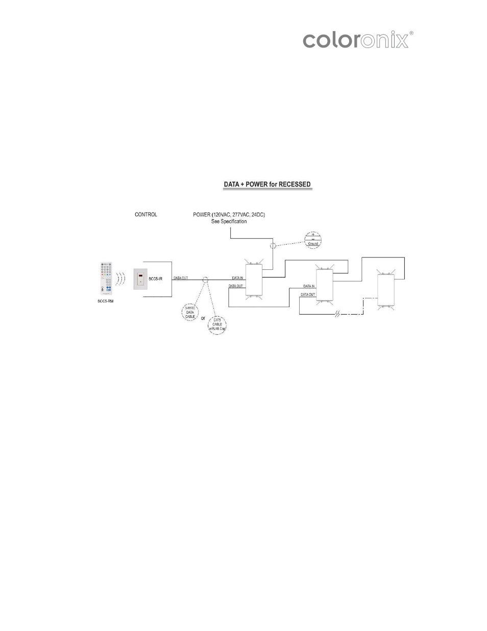
Electrical Connection
Electrical Connection
Electrical Connection
Electrical Connection
NOTE: Supply lead wires should not be connected to a dimmer of any sort.
Installing Your SCC5-IR Receiver
1. Prepare Wires:
Note: Make sure the low-voltage wiring is installed at the wall box that will house the Color Ray
receiver.
•
Be sure that the ends of the wires from the wall box are straight—cut if necessary.
•
Remove 5/8” or 1.6 cm of insulation from each wire in the wall box.
2. Connect CAT5/RJ45 Cable to on board RJ45 jack.
3.
Connect Power
Connect the line voltage (120V) wires in the following manner:
Screw the wire nuts clockwise so that no bare conductors show below the wire
connectors. Secure each connector with the electrical tape.
•
Green dimmer Ground lead to Green or bare copper wire in wall box.
4. Test the Color Ray Receiver prior to mounting in wall box:
•
Restore the power at the circuit breaker or fuse.
•
Turn remote on to test.
•
If the lights still do not turn on, refer to the troubleshooting section.
Note: set
all fixtures to DMX address 1 (dip switch 1 in the UP position in Coloronix fixtures with Dip
Switches)
5.
Mounting
1. Turn off the power at the circuit breaker or fuse.
2. Carefully position all wires so that there is room for the wall box for the dimmer.
3.
Mount the dimmer into the box with the supplied mounting screws.
4. Attach the wallplate.
5.
Complete the installation by restoring power at the circuit breaker or fuse.