Crydom SOLICON DRC Series User Manual
Installation sheet, Din rail mount, 48 d 3p
Do not forget to visit us at:
www.crydom.com
Copyright © 2014 Custom Sensors & Technologies. Specifications subject to change without notice.
Installation Sheet
DIN Rail Mount
Rev. 011414
SOLICON DRC Series 3 Phase & Reversing
Solid State Contactors
DIN Rail Mount
This installation sheet includes detailed mounting and wiring instructions which apply
for Crydom SOLICON DRC 3 Phase and Reversing Solid State Contactors. Be sure to
visit the product series' datasheet available at the Crydom website to complement
this information. If you have questions or need additional information please contact
Crydom Tech Support.
Please read all mounting instructions before using your SOLICON DRC Series Solid State
Contactor.
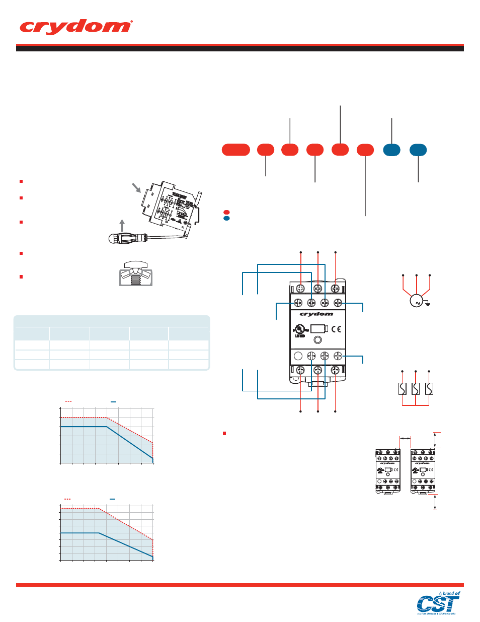
PART NUMBER NOMENCLATURE
General Notes
(A)
See compatible accessories in corresponding datasheet.
(B)
To achieve maximum ratings, there must be a minimum spacing of 0.8 in (22 mm) between the devices in free air
and a minimum free spacing of 3.15 in (80 mm) at the top and at the bottom. (see fig. 3)
(C)
Normally Open (13 - 14) for DRC3xxxx411 models and DRC3xxxx420 models.
(D)
Normally Open (23-24) for DRC3xxxx420 models, Normally Closed (21-22) for DRC3xxxx411 models.
(E)
Not available for DRC3xxxx400 models.
DRC
Series
Operating Voltage
40: 400 VAC
(3R function only)
48: 480 VAC
Control Voltage
A: 230 VAC
B: 120 VAC
D: 24 VAC/DC
Function
3P: Three Phase
3R: Reversible
48
D
3P
Load Current per Phase
4: 7.6 Amp FLA
(x2 Controlled Legs
& 3R function);
4.8 Amp FLA
(x3 Controlled Legs only)
4
Auxiliary Contacts,
N.O. - N.C.
00: Not included
11: 1 Solid State Auxiliary
Contact, Normally Open;
1 Solid State Auxiliary
Contact, Normally Closed
(3P function only)
20: 2 Solid State Auxiliary
Contacts, Normally Open
00
Switching Mode
(3P function only)
Blank: Zero Voltage Turn-On
R: Instantaneous Turn-On
Controlled Legs
(3P function only)
Blank: 3 Controlled Legs
2: 2 Controlled Legs
R
2
Required for valid part number
For options only and not required for valid part number
3 HP / 2.2 KW
2 HP / 1.5 KW
1 HP / 0.75 KW
40ºC
60ºC
80ºC
DRC3P48xx
@ 480 VAC
5 HP / 3.7 KW
3 HP / 2.2 KW
1.5 HP / 1.1 KW
DRC3P48xx2
@ 480 VAC
Temperature
TABLE 1. HP Ratings at Nominal Voltage
3 HP / 2.2 KW
2 HP / 1.5 KW
3/4 HP / 0.55 KW
DRC3R40xx
@ 400 VAC
5 HP / 3.7 KW
3 HP / 2.2 KW
1 HP / 0.75 KW
DRC3R48xx
@ 480 VAC
(B)
DERATING CURVES
(B)
Ambient Temperature (ºC)
Load Current (Amps)
DRC3Pxx-2 (2 legs controlled) & DRC3R
Single unit
Multiple units
8
7
6
5
4
3
2
1
0
20
10
30
40
50
60
70
80
0
(B)
6
5
4
3
2
1
10
0
20
30
40
50
60
70
80
0
Ambient Temperature (ºC)
Load Current (Amps)
DRC3Pxx (3 legs controlled)
Single unit
Multiple units
WIRING DIAGRAM
MOUNTING INSTRUCTIONS
Install the contactor on the DIN
rail (as shown in fig.1).
Wire the contactor to the input
side. AWG #18 (0.8 mm
2
) minimum,
AWG #12 (3.3 mm
2
) x 2 maximum.
Wire the contactor to the output
side. AWG #18 (0.8 mm
2
) minimum,
AWG #10 (5.3 mm
2
) x 2
(stranded/solid) maximum.
Maximum recommended terminal
screw torque input 12 in-lbs (1.36
Nm) & output 15 in-lbs (1.7 Nm).
If multiple units are installed be
sure to follow derating curves
(A)
To remove from
DIN rail
To install on DIN rail
fig. 1
WARNING! Removing product from 35 mm rail incorrectly by not using the
appropriate tool could damage the latching system
Important Considerations
Be sure to use input and output voltages within operating
ranges.
L
ED indicates only input status. It does not represent output
status.
To achieve maximum ratings, there must be a minimum
spacing of 0.8 in (22 mm) between the devices in free air and
a minimum free spacing of 3.15 in (80 mm) at the top and at
the bottom. (See fig. 3)
INPUT
STATUS
13
21/23
A1
A3
14
22/24
A2
L1
L2
L3
T1
T2
T3
XXXX
IND. CONT. EQ.
DRC3
CONTROL
INPUT
(Backward)
[DRC3R
model only]
CONTROL
INPUT
(Forward)
COMMON
FOR CONTROL
INPUT
1st Auxiliary Contact
(18 - 280 V
AC)
2nd Auxiliary Contact
(18 - 280 V
AC)
(C,E) (D,E)
L1
L2
L3
T1
T2
T3
T1
T2
T3
M
3
Motor Controller /
AC-53 Application
Overload current
protection needs to
be considered
T1
T2
T3
General Use /
AC-51 Application
0.9 in
[22 mm]
Minimum
3.15 in
[80 mm]
Minimum
3.15 in
[80 mm]
Minimum
fig. 3
Multiple units mounting for maximum ratings
fig. 2
Terminal
screw type.
Top/Bottom view.