2 single-court scoreboard mounting, Clamping angles, Single-court scoreboard mounting – Daktronics TN-2601 Outdoor LED Tennis Scoreboard User Manual
Page 10
4
Mechanical Installation
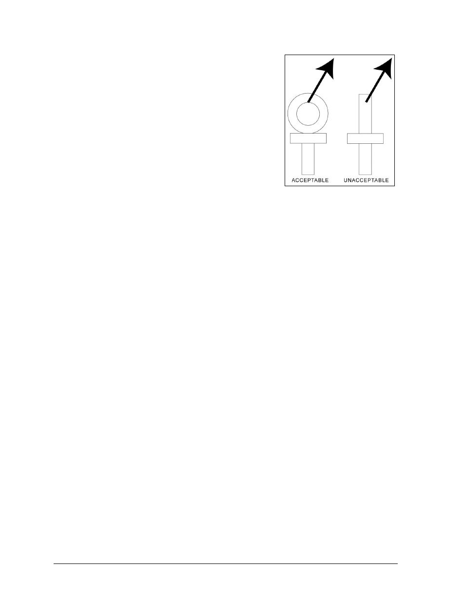
Do NOT attempt to lift the display if the angle is less than
45°. Exceeding load angles or weight limits could cause
the bolts in the scoreboard cabinet to buckle, resulting in
serious damage to the scoreboard or injury to personnel.
Also, loads should be applied directly in the plane of the
eyebolt as shown in Figure 4.
Note: Daktronics assumes no liability for damages
resulting from incorrect setup or lifting methods.
Eyebolts are intended for lifting only. Do not attempt
to permanently support the display by the eyebolts.
If installers remove the eyebolts, plug the holes with bolts
and the rubber washers that are used with the eyebolts.
Apply silicone or another waterproof sealant to the
eyebolt openings. Also inspect the top and sides of the
display for any other holes or openings that may allow
moisture to enter the display and plug and seal those openings.
2.2 Single-Court Scoreboard Mounting
Two standard mounting methods are available for Daktronics single-court tennis scoreboards.
Clamping Angles
Mounting hardware includes C-channels; rear clamping angles;
1
/
2
-13 x 15" threaded rods;
and
1
/
2
" square nuts, hex nuts, and lock washers. Refer to Figure 5 and Drawing A-1130246
in Appendix B.
1. Position the scoreboard at the front of the beams, and lift it to the desired height.
2. Place a C-channel against the upper rear flange of the scoreboard next to each beam.
3. With the C-channel as a template, use a
9
/
16
" bit to drill holes in the upper rear flange
of the scoreboard cabinet where the rods will pass through. The rods should be as
close to the beam as possible.
4. Push the rods through the holes in the rear flange of the scoreboard cabinet and into
the C-channel, and then thread
1
/
2
" square nuts onto the rods inside the C-channel.
5. Place clamping angles over each pair of rods and secure with
1
/
2
" lock washers and
hex nuts.
6. Make final adjustments in the positioning of the scoreboard to ensure it is flush and
level, and then firmly tighten all of the
1
/
2
" hex nuts.
7. Repeat steps 2-6 for the lower rear flange of the scoreboard for every beam.
Figure 4: Eyebolt Plane Load
- TN-2603 Outdoor LED Tennis Scoreboard TN-2604 Outdoor LED Tennis Scoreboard TN-2605 Outdoor LED Tennis Scoreboard TN-2606 Outdoor LED Tennis Scoreboard TN-2607 Outdoor LED Tennis Scoreboard TN-2650 Outdoor LED Tennis Scoreboard TN-2651 Outdoor LED Tennis Scoreboard TN-2652 Outdoor LED Tennis Scoreboard TN-2653 Outdoor LED Tennis Scoreboard TN-2654 Outdoor LED Tennis Scoreboard TN-2655 Outdoor LED Tennis Scoreboard TN-2656 Outdoor LED Tennis Scoreboard TN-2657 Outdoor LED Tennis Scoreboard P1647 Single-Section Outdoor LED Scoreboard P1647 Multi-Section Outdoor LED Scoreboard FB-2500 Modular LED Football Scoreboard FB-2600 Modular LED Football Scoreboard