3 power-on self-test (post), Power-on self-test (post) – Daktronics P1647 Multi-Section Outdoor LED Scoreboard User Manual
Page 20
14
Electrical Installation
Refer to the component location drawings attached to the product specification sheets listed
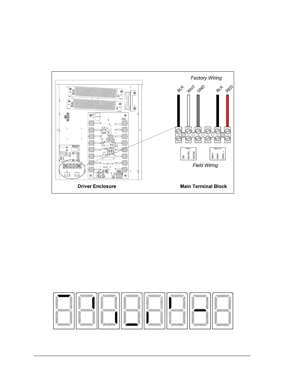
in Appendix A for precise power/signal termination location for each model.
Connect the appropriate wires coming through the rear of the scoreboard to the main
terminal block, as shown in Figure 14. Note that SIGNAL OUT connects here as well.
Note: If a power receptacle is needed to operate the control console at the scoreboard for
troubleshooting, Daktronics recommends that an installation electrician provides a 120 V
outlet close to the disconnect box specifically for this purpose.
3.3 Power-On Self-Test (POST)
The scoreboard performs a self-test each time that power is turned on and the control console
is powered off or not attached to the scoreboard. If the control console is attached and
powered on, the self-test does not run, and data from the control console is displayed on the
scoreboard after a brief period of time. Each scoreboard self-test pattern will vary depending
on the scoreboard model, the number of drivers and types of digits. Figure 15 shows an
example of the LED bar test pattern that each digit performs.
Figure 14: Driver Enclosure & Power Terminal Block
Figure 15: Digit Segment POST