For tnmcs built before september 2009 – Daktronics Single-Section Outdoor LED Scoreboards User Manual
Page 29
TNMC Troubleshooting & Maintenance
23
For TNMCs Built Before September 2009
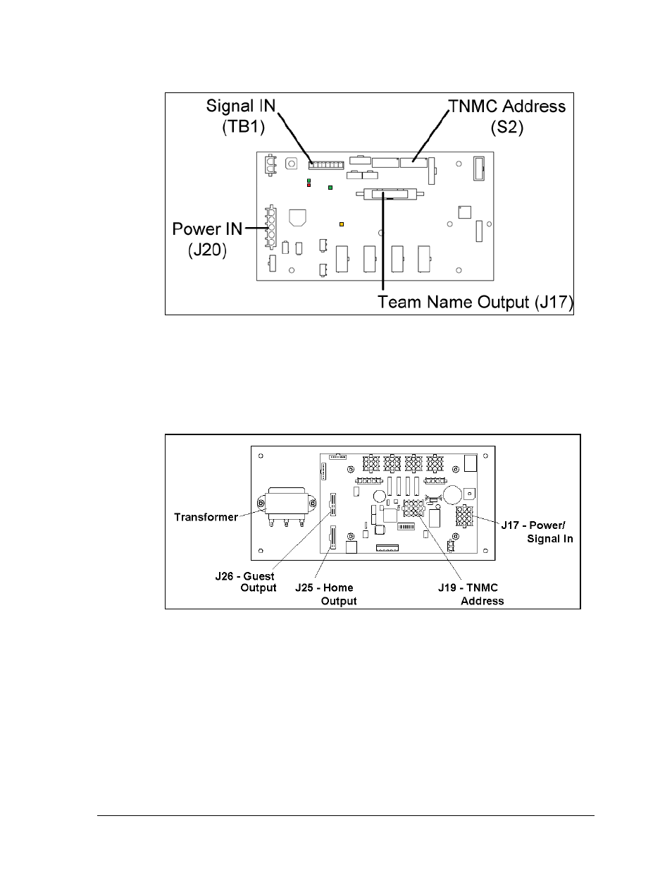
The TNMC driver receives signal from the control console via a signal surge arrestor card
and sends data to the modules. Refer to Section 3.4 for more information on signal routing.
The driver itself is detailed in Drawing A-166216 in Appendix C. Figure 25 illustrates a
TNMC control assembly with a 4-column MASC driver.
Connectors J25 and J26 control Home and Guest displays. When the ribbon cable is plugged
into J25, the TNMC displays home team information. In the opposite message center, the
signal cable should be plugged into the J26 connector to display guest information.
J19 is the connector for the address plug. The address setting for a TNMC will always be 221.
(There may be other settings if the TNMC is used to display messages other than team names.)
Figure 24: 4 Column MCAST Driver
Figure 25: TNMC Control Assembly (4 Column MASC Driver)