Daktronics Data Time Series 50 Time & Temperature Displays User Manual
Page 50
Maintenance &
Troubleshooting
5-4
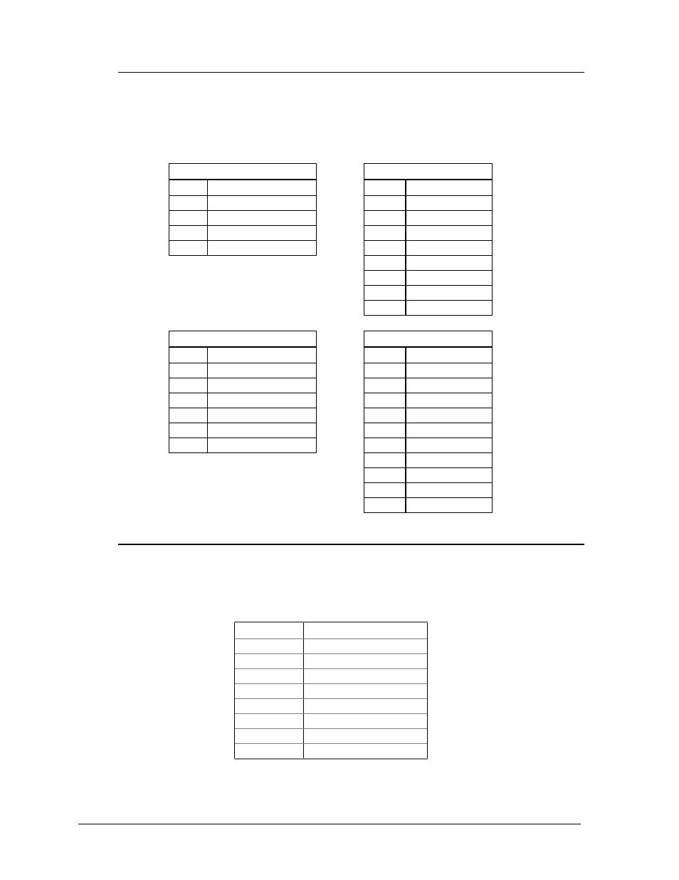
5.2.1 Connectors
The controller receives input from the temperature sensor (TB2) and handset (TB3)
and sends out data to the lamp driver (TB1). Power is brought into the controller on
J1. Refer to Drawing A-37070 for locations of these connectors on the controller.
The following tables show the pin functions of the jack and terminal blocks.
J1
TB1
Pin
Function
Pin
Function
1
Power (10 VAC)
1
Data Out 1+
2
Power (10 VAC)
2
Data Out 1-
3
Reset
3
Data Out 2+
4
Reset Ground
4
Data Out 2-
5
Switch 1+
6
Switch 1-
7
Switch 2+
8
Switch 2-
TB2
TB3
Pin
Function
Pin
Function
1
Photocell
1
RX (Handset)
2
GND
2
TX
3
+5 Volts
3
CTS
4
GND
4
RTS
5
Temp. In
5
GND
6
GND
6
+5 Volts
7
Network +
8
Network -
9
C.L. +
10
C.L. -
5.2.2 Switches
Refer to Drawing A-37070 for the location of the DIP switch package on the
controller. The following table shows the function of each switch. Refer to Section
4.8 for additional switch setting information.
Switch #
Function
1
Lamp Test
2
Alternate Test
3
Real Time Clock
4
12/24 Hour
5
Daylight Savings
6
Indoor Controller
7
8 Column Driver
8
7/8 Segment Mode