Daktronics DF-12xx User Manual
Page 20
2-8 Electrical
Installation
1. Using the DB9M to DB9F serial cable, connect from the DataMaster
controller to the modem/j-box, at the “DB9 Male, DataMaster 100
connect” jack.
2. Connect a phone line from a phone junction box to the modem/j-box jack
labeled “Phone Line Connection”.
3. Plug the wall pack transformer into the modem/j-box and then into a
120V grounded outlet.
4. At the display, the local phone company must provide a dedicated phone
line to the display and identity the color used for the “Tip” wire and
which color is for the “Ring”.
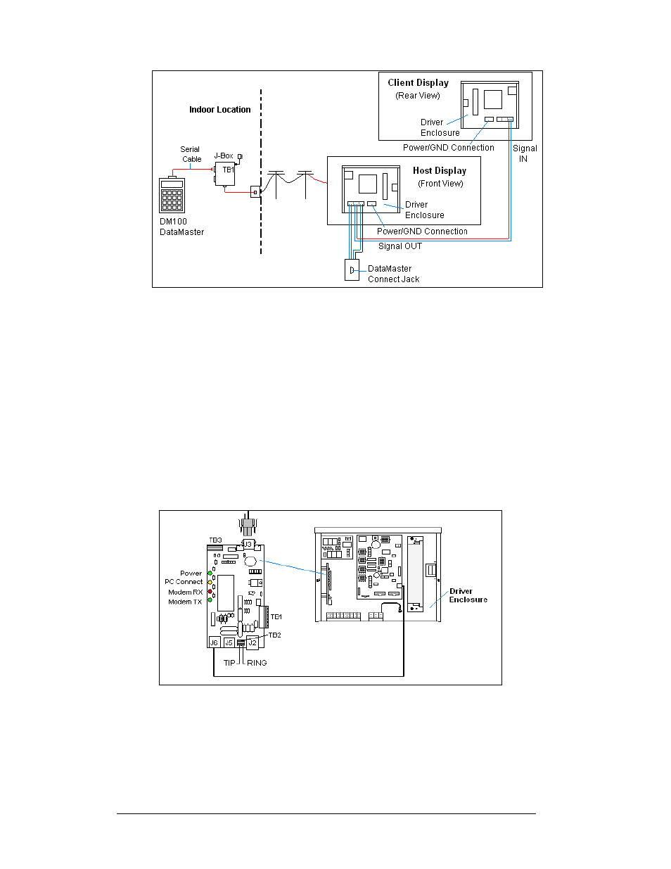
5. The Tip and Ring phone wires will terminate to TB2 on the modem as
shown in Figure 7 and Drawing A-177039. If a phone cable is used, it
will plug into J5.
Notes:
1. A current-loop j-box is often mounted at the base of the display pole for
communication in the case of problems with the phone line.
2. The phone line and display power cannot be routed though the same
conduit.
Figure 6: Modem Controlled Display Layout
Figure 7: Phone line Connection to Display Modem