Daktronics AF-3020-7.6-R,A User Manual
Page 33
Reference Drawings:
System Riser Diagram (Modem) ........................................................... Drawing A-88426
Power / Signal Termination Panel ......................................................... Drawing A-88427
System Riser Diagram (422) ................................................................. Drawing A-92681
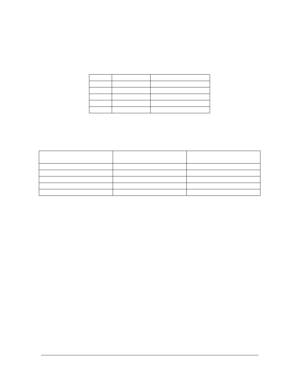
A 4-conductor cable with shield is used to connect the temperature sensor to the display. The cable is
terminated in the entrance enclosure on the terminal block labeled “TEMP SENSOR.”
TB42
Cable Wires
Temperature Sensor
Pin 7
Green
Temp RX-P
Pin 8
White
Temp RX-N
Pin 9
Red
Temp +5V
Pin 10
Black
Temp GND
Pin 10
Bare
N/A
2V Displays
If the display is 2V, one temperature sensor is used for both sides. An extra piece of the 4-conductor
cable must be used to jumper the temperature sensor data to the second sign. Refer to Drawings
A-88426, A-88427 and A-92681 (located at the end of Section 3) for connections. Note: Do not
connect the red, black or shield wires in the jumper to the second sign.
Sign A
(TB43)
Field Cabling
Sign B
(TB42)
Pin 7
Green
Pin 7
Pin
8 White Pin
8
NC Black NC
NC Red NC
NC Blue NC
A-2
Appendix A: Optional Temperature Sensor