Fiber optic, Fiber optic -14, Figure 29: fiber display layout -14 – Daktronics AF-3160-34-R,A User Manual
Page 32: Figure 30: signal converter to fiber card -14
Fiber Optic
Reference Drawings:
System Riser Diagram Fiber ....................................... Drawing A-174344
Schematic, Signal Wiring, Internal, W/Quick Connect Drawing B-177662
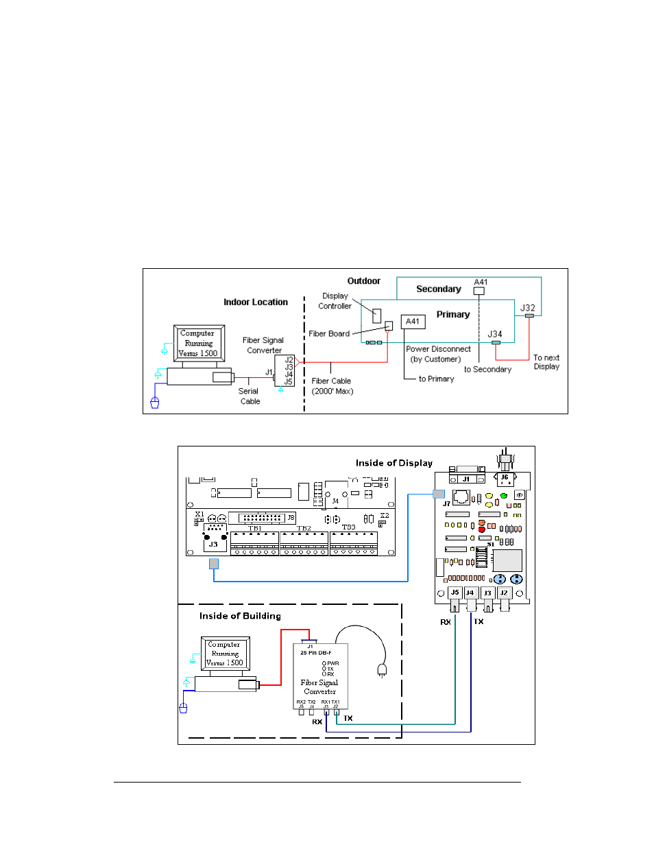
When fiber optic cable is used, a signal converter (0A-1127-0239), connected to the
computer, relays signal via fiber signal cable to the fiberboard (J4/J5) in the display.
An 8-conductor cable with RJ45 connectors (Daktronics part number 0A-1229-0054)
relays the signal from J7 on the fiberboard to J3 (RS232 IN) on the controller. When
connecting fiber cables, always connect transmit at the signal converter to receive at
the display and receive to transmit. Refer to Drawing A-174344 and
for
the system riser and to Drawing B-177662 and
for fiber termination
locations.
Figure 29: Fiber Display Layout
Figure 30: Signal Converter to Fiber Card
Electrical Installation
3-14