DFI CP908-B User Manual
Page 32
Advertising
32
2
Hardware Installation
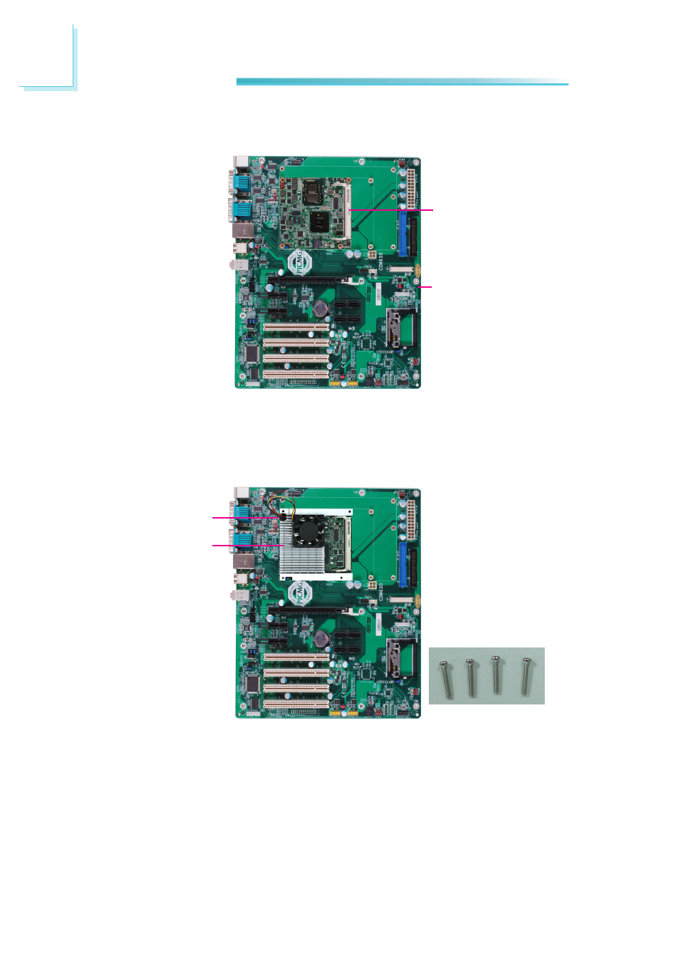
8. Position the heat sink on top of CP908-B with the heat sink’s mounting holes
aligned with CP908-B’s mounting holes. Use the provided long screws to se-
cure the heat sink to the board and then connect the cooling fan’s cable to
the fan connector on CP908-B.
Carrier board
Mounting screws
Fan cable
7. Press CP908-B down firmly until it is completely seated on the COM Express
connectors of the carrier board.
CP908-B
Heat sink
Advertising
See also other documents in the category DFI Hardware:
- ES300 (2 pages)
- U340 Series (2 pages)
- VS Series (2 pages)
- BT9A3 (57 pages)
- CD9A3 series (60 pages)
- CD905-B series (68 pages)
- BT700 (71 pages)
- BT700 (71 pages)
- CD905-B2600 (63 pages)
- CD905-B2800 (63 pages)
- CR908-B (68 pages)
- HR908-B (66 pages)
- HU968 (86 pages)
- ML905-B11C/B16C (76 pages)
- KB968 (68 pages)
- LR905-B18S (93 pages)
- OT905-B series (61 pages)
- CM960-B (1 page)
- CM901-B (72 pages)
- CP900-B (130 pages)
- NP905-B16C (125 pages)
- CR900-B (73 pages)
- CR902-BL (75 pages)
- CR901-B (69 pages)
- CR960-QM77 (81 pages)
- HM920-QM87 (98 pages)
- G5C900-B106 (118 pages)
- HM960-QM87 (101 pages)
- HM961-QM87 (95 pages)
- HR900-B (102 pages)
- HR902-BL (75 pages)
- FS700 (17 pages)
- QB702-B (47 pages)
- QB700-B (73 pages)
- COM100-B (32 pages)
- QB701-B (73 pages)
- NP900-B16C (121 pages)
- COM101-BAT (32 pages)
- COM630-B (50 pages)
- COM330-B (57 pages)
- Q7-100 (31 pages)
- Q7-951 (46 pages)
- Q7A-551 (23 pages)
- Q7X-151 (30 pages)