Chapter 2 – DFI Q7A-551 User Manual
Page 10
Advertising
www.dfi .com
Chapter 2 Hardware Installation
10
Chapter 2
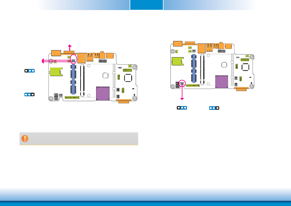
Touch Panel Power Select
1-2 On:
+3V_standby
2-3 On: +5V_standby
(default)
JP3
1
3 2
1
3 2
JP3 controls the power level of the touch panel IC.
COM RS232/UART5 Select
JP11
JP12
1-2 On:
RS232 (default)
2-3 On: UART5
1
3 2
1
3 2
JP11 and JP12 are used to configure the COM port to RS232 (default) or UART5.
Important:
You need to set JP11 and JP12 simultaneously.
COM
Advertising
See also other documents in the category DFI Hardware:
- ES300 (2 pages)
- U340 Series (2 pages)
- VS Series (2 pages)
- BT9A3 (57 pages)
- CD9A3 series (60 pages)
- CD905-B series (68 pages)
- BT700 (71 pages)
- BT700 (71 pages)
- CD905-B2600 (63 pages)
- CD905-B2800 (63 pages)
- CP908-B (104 pages)
- CR908-B (68 pages)
- HR908-B (66 pages)
- HU968 (86 pages)
- ML905-B11C/B16C (76 pages)
- KB968 (68 pages)
- LR905-B18S (93 pages)
- OT905-B series (61 pages)
- CM960-B (1 page)
- CM901-B (72 pages)
- CP900-B (130 pages)
- NP905-B16C (125 pages)
- CR900-B (73 pages)
- CR902-BL (75 pages)
- CR901-B (69 pages)
- CR960-QM77 (81 pages)
- HM920-QM87 (98 pages)
- G5C900-B106 (118 pages)
- HM960-QM87 (101 pages)
- HM961-QM87 (95 pages)
- HR900-B (102 pages)
- HR902-BL (75 pages)
- FS700 (17 pages)
- QB702-B (47 pages)
- QB700-B (73 pages)
- COM100-B (32 pages)
- QB701-B (73 pages)
- NP900-B16C (121 pages)
- COM101-BAT (32 pages)
- COM630-B (50 pages)
- COM330-B (57 pages)
- Q7-100 (31 pages)
- Q7-951 (46 pages)
- Q7X-151 (30 pages)