Chapter 2 – DFI BT100 User Manual
Page 30
www.dfi .com
30
Chapter 2 Hardware Installation
Chapter 2
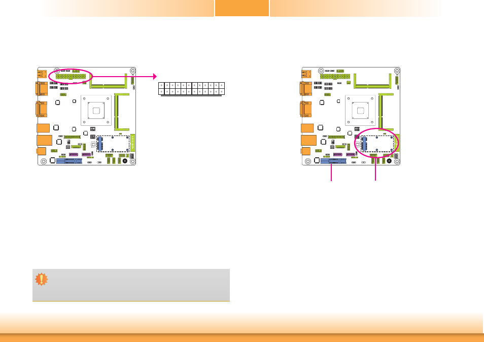
ATX Power Connector
13
12
24
1
+3.3VDC
+3.3VDC
GND +5VDC GND +5VDC
GND
PWR_OK +5VSB +12VDC +12VDC +3.3VDC
+3.3VDC
-12VDC
GND
PS_ON#
GND GND GND
NC
+5VDC
+5VDC +5VDC
GND
ATX
power
Expansion Slots
Mini PCIe Slot
The Mini PCIe socket is used to install a half size Mini PCIe card. Mini PCIe card is a small
form factor PCI card with the same signal protocol, electrical definitions, and configuration
definitions as the conventional PCI. It supports PCIe and USB signals.
PCI Express x4 Slot
Install PCI Express cards such as network cards or other cards that comply to the PCI Express
specifications into the PCI Express x4 slot.
PCI Express x4
Mini PCI Express
Use a power supply that complies with the ATX +12V Power Supply Design Guide Version 1.1.
An ATX +12V power supply unit has a standard 24-pin ATX main power connector that must
be inserted into the 24-pin connector.
The power connector from the power supply unit is designed to fit the 24-pin connector in
only one orientation. Make sure to find the proper orientation before plugging the connectors.
The system board requires a minimum of 300 Watt power supply to operate. Your system
configuration (CPU power, amount of memory, add-in cards, peripherals, etc.) may exceed the
minimum power requirement. To ensure that adequate power is provided, we strongly recom-
mend that you use a minimum of 400 Watt (or greater) power supply.
Important:
Insufficient power supplied to the system may result in instability or the add-in boards
and peripherals not functioning properly. Calculating the system’s approximate power
usage is important to ensure that the power supply meets the system’s consumption
requirements.