Chapter 2 – DFI RL830-C602/C604 User Manual
Page 23
www.dfi .com
23
Chapter 2 Hardware Installation
Chapter 2
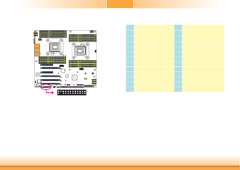
Front Panel Connector
Front Panel
R227
U19
C170
7
6
R227
U19
C170
7
6
2
1
24
23
Pins
Pin Assignment
Pins
Pin Assignment
1
+3VDU
2
+3VDU
3
N.C
4
+5VDU
5
PWR-LED
6
x
7
+3.3V
8
x
9
HDD-LED
10
x
11
PWR-BTN
12
LED_NIC_LINK1_0_LINKUP
13
GND
14
LED_NIC_LINK1_0_ACT
15
RST-SW
16
SMB_SENSOR_3V3STBY_DATA
17
GND
18
SMB_SENSOR_3V3STBY_CLK
19
x
20
Case Open
21
+3VDU
22
LED_NIC_LINK3_2_LINKUP
23
x
24
LED_NIC_LINK3_2_ACT
HDD-LED - HDD LED
This LED will light when the hard drive is being accessed.
RESET SW - Reset Switch
This switch allows you to reboot without having to power off the system.
PWR-BTN - Power Switch
This switch is used to power on or off the system.
PWR-LED - Power/Standby LED
When the system’s power is on, this LED will light.
The pin functions of the front panel connector are listed below.