Installation, Select remote mode on the vtr's front panel, Connection diagram – DNF Controls ST304-Edit User Manual
Page 8: Installation 4, Iii. installation, Iv. connection diagram
III. INSTALLATION
i)
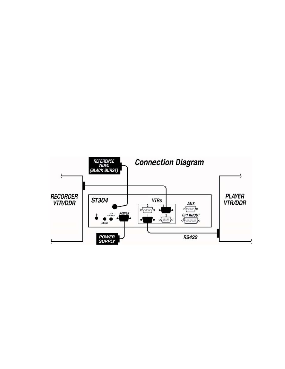
Plug one end of a 9-conductor, RS422 serial cable into the VTR1, VTR2, VTR3, or
VTR4 connector on the rear of the ST304. Plug the other end of the cable into the 9-pin
REMOTE connector on the VTR.
ii) Connect Black Video to the Reference Video BNC on the rear of the ST304.
iii) NOTE: The ST304 will perform edits without reference. Reference Video is required
for frame accurate edits.
iv) Plug the Power Supply into an outlet, 90 VAC – 240 VAC.
v) Select REMOTE mode on the VTR's front panel.
vi) Check the SETUP MENU prior to using the Slow Motion Controller to confirm proper
Record mode, SLO-MO speed range, and other User settable modes.
IV. Connection diagram
4
S
S
T
T
3
3
0
0
4
4
-
-
E
E
D
D
I
I
T
T
&
&
S
S
T
T
3
3
0
0
4
4
-
-
E
E
D
D
I
I
T
T
-
-
T
T
,
,
S
S
l
l
o
o
w
w
M
M
o
o
t
t
i
i
o
o
n
n
C
C
o
o
n
n
t
t
r
r
o
o
l
l
l
l
e
e
r
r