Gpi connection diagram, Gpis, wet/ dry configuration – DNF Controls USP-S User Manual
Page 24
Page 24 of 27
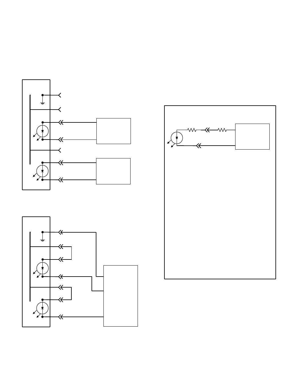
15. GPIs, WET/ DRY Configuration
EXAMPLE #1- Device Powered GPIs
EXAMPLE #2- WET GPIs using internal +5V
1
13
23
25
11
Internal +5VDC
GPI Connector
12
24
GPI #1 (+)
GPI #1 (-)
GPI #2 (+)
GPI #2 (-)
DEVICE #2
+12V
GPO #1
DEVICE #1
+5V
GPO #1
Ground
GPO
provides
path to
ground
GPO
provides
path to
ground
1
13
23
25
11
In
te
rn
al +
5V
D
C
12
24
GPI #1 (+)
GPI #1 (-)
GPI #2 (+)
GPI #2 (-)
Wire
Jumper
Wire
Jumper
DEVICE #3
GPO #1
GPO #2
Ground
GPO
provides
path to
ground
GPI Connector
Specification for GPI input:
1. Voltage: (Internal resistor only)
+3.3V minimum
+5V typical
+6V maximum
2. Current: (Internal resistor only)
5mA minimum
10mA typical
15mA maximum
For typical 10mA current, if external voltage is
higher than +5V, a series resistor is required:
R
ext
= (V
ext
- 4.5) / 0.01
V
ext
= +9V => R
ext
= 450 Ohms
V
ext
= +12V => R
ext
= 750 Ohms
V
ext
= +24V => R
ext
= 1950 Ohms
GPI Technical Data
R
Internal
330 Ohms
R
External
External
Device
Ground
Power
GPI CONNECTION DIAGRAM