Rear panel connections 3, Installation – Drake DDC864A Digital Down Converter User Manual
Page 2
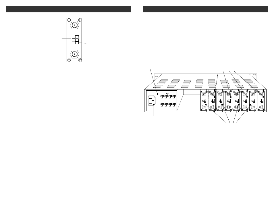
REAR PANEL CONNECTIONS 3
Figure 2
R1
R2
R3
R1 - IF OUTPUT Connector
This is the 44 MHz IF output. The level is
+30 dBmV.
R2 - DC INPUT Connector
This 3-pin connector (Male) accepts the
appropriate mating DC power cable. Observe
proper orientation and wiring.
R3 - RF IN Connector
This is the downconverter RF input from an
antenna or CATV feed.
+12 V
GND
+5 V
POWER
+12 V
GND
+5 V
IF OUT
RF IN
4
INSTALLATION
CONNECTIONS AND CONTROLS
All connections to and from each upconverter
are made through the rear panel.
DESCRIPTION
Figure 3 shows a typical installation utilizing the
Drake DRMM12 rack with 4 DDC864A
downconverters, and 4 DUC upconverters.
A PS8 power supply module is used to power all
units.
Figure 3
AC POWER
CONNECTOR
RACK MOUNTING
Adequate ventilation is very important in
multichannel installations. Units should be
spaced apart vertically by at least 1.75"
wherever possible, and some air movement is
mandatory in enclosed rack cabinets.
Excessive heat will shorten component life and
performance will be degraded without
proper cooling.
POWER
SUPPLY
DDC864A
DIGITAL
DOWNCONVERTERS
DUC864
UPCONVERTERS
100-240 V ~
50/60 Hz
85 WATTS
12V GND 5V
DC OUTPUTS X 8
DC OUTPUT RATING.
TOTAL OF ALL OUTPUTS: +5V:6A MAX.
+12V:2.5A MAX.
RF IN
IF OUT
+5 V
GND
+12 V
POWER
IF IN
POWER
+12 V
GND
+5 V
RF OUT
RF IN
IF OUT
+5 V
GND
+12 V
POWER
IF IN
POWER
+12 V
GND
+5 V
RF OUT
RF IN
IF OUT
+5 V
GND
+12 V
POWER
IF IN
POWER
+12 V
GND
+5 V
RF OUT
RF IN
IF OUT
+5 V
GND
+12 V
POWER
IF IN
POWER
+12 V
GND
+5 V
RF OUT