Fenix EBERLE AZT-A (AZT-I) 524 410 (510) User Manual
Allzweckthermostat – elektronisch, General purpose electronic thermostat
U 468 931 000 862-03
1. Verwendungszweck
Der Allzweckthermostat wird zur Regelung
der Heizung oder Ventilatoren in feuchten
oder staubigen Räumen eingesetzt, z. B.
Garagen, Lagerräume, Waschräume, Ställe,
Gewächshäuser etc.
2. Montage
Der Montageort sollte so gewählt werden, daß
das Gerät keiner dauernden Zugluft oder
Wärmestrahlung ausgesetzt und eine unge-
hinderte Luftzirkulation gewährleistet ist. Mon-
tagehöhe ca. 1,6 m.
Bei Außenmontage ist die Nordseite des Ge-
bäudes vorzuziehen. Ist das nicht möglich,
muß als Schutz gegen direkte Sonnenein-
strahlung ein Abschirmblech montiert werden.
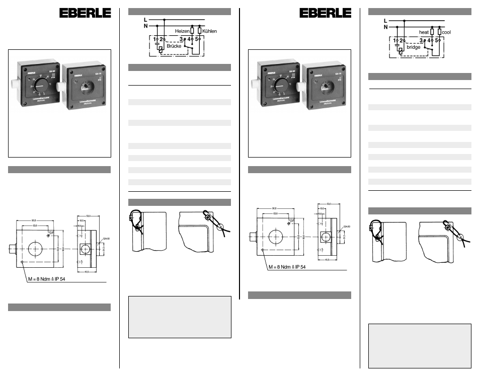
3. Anschlußschaltbild
4. Technische Daten
Best.-Nr.
EDV-Nr.
Temperatur-
bereich
Regler mit Außeneinstellung
AZT-A 524 510
0524 60 140 510
+ 5 bis +35 °C
AZT-A 524 410
0524 60 141 410
–15 bis +15 °C
Regler mit Inneneinstellung
AZT-I 524 510
0524 61 140 510
+ 5 bis +35 °C
AZT-I 524 410
0524 61 141 410
–15 bis +15 °C
Netzversorgung
Nennspannung 50 Hz
220 V
Toleranzbereich
187… 242 V
Schaltstrom
10 A / 250 V
Schaltleistung
2,5 KVA
Kontakt
1 Wechsler
Zul. Umgebungstemperatur
–20 bis +40 °C
Schalttemperaturdifferenz
ca. 0,5 K
Schutzart Gehäuse nach DIN 40 050
IP 54
Fühler
NTC linearisiert
Gewicht
ca. 250 g
5. Plombierung des Gehäuses
1.
Rechte obere Deckelschraube ersetzen
durch beiliegende Plombierschraube (mit
Querloch).
2. Plombierdraht durch Kanal im Deckel und
Plombierschraube ziehen und Plombe
setzen.
ACHTUNG
Das Gerät darf nur durch einen Fachmann installiert
bzw. eingesetzt werden. Dabei sind die bestehen-
den Sicherheitsvorschriften zu beachten.
Die Möglichkeiten der Anwendung und Dimensio-
nierung insbesondere die techn. Daten ergeben
sich aus unseren Prospektangaben.
Allzweckthermostat
– elektronisch –
Typ AZT-A 524 410 / 510
Typ AZT-I 524 410 / 510
Montage- und
Bedienungsanleitung
K
EBERLE Controls GmbH
Postfach 13 01 53 · D-90113 Nürnberg
Klingenhofstraße 71 · D-90411 Nürnberg/Germany
Tel. 0911 56 93 0 · Telefax 0911 56 93 214
1. Application
This thermostat is for controlling heating or
cooling in damp or dusty rooms e.g. garages,
storerooms, toilets, stables, laundries etc.
2. Mounting
The control should be mounted on an inside
wall approx 5’ from floor level (1.6 m). Avoid
draughts, direct heat from radiators, sunshine
or heated walls (airing cupboards or chimney
breasts).
For external mounting the north side of hous-
es is preferred. If this is not possible the con-
trol must be shielded from direct sunlight, wind
and rain.
3. Wiring diagram
4. Technical Data
Order No.
Comp. No.
Temp. Range
Controller with External Adjustment
AZT-A 524 510
0524 60 140 510
+ 5 ° to +35 °C
AZT-A 524 410
0524 60 141 410
–15 ° to +15 °C
Controller with Internal Adjustment
AZT-I 524 510
0524 61 140 510
+ 5 to +35 °C
AZT-I 524 410
0524 61 14 1 410
–15 to +15 °C
Operating voltage 50 Hz
220 V
Tolerance
187… 242 V~
Switching capacity
10 A / 250 V~
Switching load
2.5 KVA
Contacts
1 c/o
Ambient Temperature
–20 to +40 °C
Switching differential
app. 0.5 K
Housing class to DIN 40 050
IP 54
Sensor
NTC Line arised
Weight
app. 250 g
5. Sealing the housing
1. The top right hand cover screw can be re-
placed by a special screw with a longer
head and with a hole drilled through its di-
ameter (screw supplied separately).
2. Pass a thin wire through this hole and also
the channel in the face of the lid and seal
the two ends in the normal manner.
General purpose
electronic thermostat
Typ AZT-A 524 410 / 510
Typ AZT-I 524 410 / 510
Installation and
operating instructions
ATTENTION
The equipment may only be installed and/or
mounted by an expert according to the existing
safety regulations.
Possible applications and dimensioning particular-
ly technical data may be found in our technical
leaflets.
Irrtum und Änderungen vorbehalten