FiberPlex MD-3 User Manual
Md-3
1
MD-3
Functional Considerations
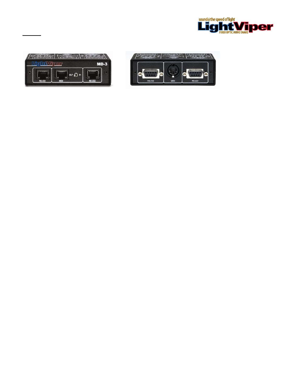
The Light Viper MD-3 is very simple device designed to translate RS-232, RS-422 and MIDI data into TTL
control data, thereby allowing it to be transported via fiber through the “control circuit” connectors that
appear on the LightViper VIS-1832, VIS-4832, VIM-1832, VIM-1032, VIM-1808 and VIM-0808. The MD-3
is designed to be used in pairs. A single MD-3 contains (1) RS-232 connector, (1) RS-422 connector, and
(1) MIDI connector located on the front of the MD-3. On the back of the unit there are (3) corresponding
RJ-45 connectors, and a switch to determine MIDI send/receive status.
Standard Components
In its standard configuration, the Light Viper MD-3 data translation and transport system consists of three
primary components:
2 ea. Of the MD-3 - This is the hardware interface. One unit is placed on each end of the data
connection.
RS-422, 232 or MIDI input / output cables – These cables connect the devices transmitting the control
signals into the MD-3 on the “send” side of the data path, as well as connecting the data output from the
MD-3 to the devices on the receiving end of the data path.
CAT-5 jumpers – one CAT-5 jumper cable at each end is required for each of the data protocols being
translated (RS-422, RS-232 or MIDI). These connect the RJ-45 connectors on the MD-3’s to the
LightViper “Control Circuits” connectors on both the send and receive end of the data path.
Getting Started
Setting up and using your Light Viper MD-3’s is quick and simple. Just follow these steps:
1. Mount (1) MD-3 close to the VIM-1832, VIM-1032 or VIM-1808 (“send” or mixer end)
2. Mount (1) MD-3 close to the VIS-1832, VIS-4832 or VIM-0808 (“receive” or stage end).
3. Connect the MD-3’s using standard DB9 (RS-422 or RS-232) control cables, or MIDI control
cables, on both send and receive ends of the data path.
4. Connect the MD-3’s to the LightViper “Control Circuit” RJ-45 connector on both ends of the data
path using CAT-5 jumper cables.
5. If using MIDI control, set the MIDI switch on the data origination end to “send”, and set the MIDI
switch on the data receive end to “receive”.