Installation – Fire Magic 3280 Series Sideburner User Manual
Page 10
CONNECTING THE GAS SUPPLY
For propane cylinders:
For connecting a propane unit to a portable propane tank,
read the safety warnings and follow the instructions in the
section SAFE USE AND MAINTENANCE OF PROPANE
GAS CYLINDERS.
Note: When a propane cylinder is installed inside
of the enclosure, the guidelines found in the
ENCLOSURE REQUIREMENTS section MUST
be followed.
For household propane or natural gas units:
CAUTION: Use only C.S.A. listed stainless-steel fl ex
connectors within the enclosure.
A REGULATOR MUST BE PROVIDED AT THE TANK OR
GAS SOURCE FOR USE WITH PROPANE.
WARNING
A rubber or plastic connector will rupture or leak,
resulting in an explosion or serious injury if used
inside the appliance enclosure.
a. Connect a
1
/
2
" fl ex connector (not included) to the
adapter found underneath the unit and route the other
end of the fl ex connector to the gas-supply stub.
b. Turn OFF the gas supply at the source. Connect a
pipe adapter fi tting (as appropriate for your setup) to
the gas-supply stub using a pipe joint compound that
is resistant to all gasses. Tighten securely. Then attach
the open end of the fl ex connector to the adapter.
Tighten securely.
c. Turn the burner control knob to the OFF position.
Turn the gas supply on. Then carefully check all gas
connections for leaks with a brush and half-soap/half-
water solution before lighting. NEVER USE A MATCH
OR OPEN FLAME TO TEST FOR LEAKS.
d. Close the dedicated gas-supply shut-off valve, then
lower the unit into place. Do not to pinch, kink, or
damage the gas connector line.
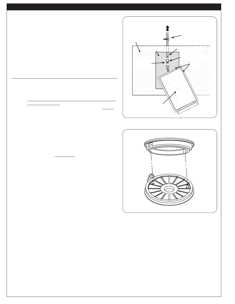
POSITIONING THE BURNER CAP
Place the burner cap so it is centered over the burner. The
burner cap has notches that fi t over the studs protruding
from the burner (see Fig. 10-2). Ensure that the cap rests
securely in place.
INSTALLATION
COUNTER PREPARATION
Consult Table 1 for enclosure cut-out dimensions. If the
counter or any supporting construction is combustible, the
COMBUSTIBLE ENCLOSURE CUT-OUT section must be
followed before beginning the installation.
This sideburner must be supported by the stainless-steel
hanger extending from the upper portion of the frame. The
hanger rests on all sides of the countertop.
Fig. 10-1 Gas connection diagram
OFF
To gas
system
Dedicated manual
shut-off valve
Gas inlet pipe
Flex
connector
Hanger
Countertop
Cut-out
Fig. 10-2 Position burner cap
Sideburner
(with lid down)
Pipe adapter fi tting
10
L-C2-025
REV 6 - 1407161320