7 setting impeller clearance – Flowserve CPXV fitted with Mark 3 ASME hydraulics User Manual
Page 27
CPXV with Mark 3 ASME hydraulics ENGLISH 71569291 12-14
Page 27 of 44
flowserve.com
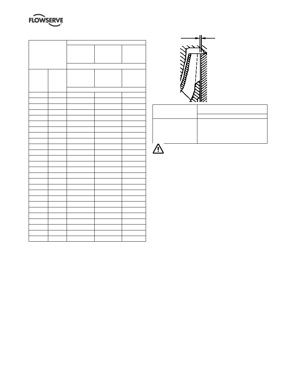
Bolt torque values for class 2 lubricated threads
Thread data
Material group
A
316 SS
B
ASTM A193
Grade B7M
4140 Steel
C
ASTM A193
Grade B8C
347H SS
Approximate yield stress N/mm
2
(psi)
Nominal
diameter
mm (in.)
Threads
per
25 mm
(1 in.)
207
(30 000)
(<400 ºC)
552
(80 000)
(<400 ºC)
138
(20 000)
(400 to
600 ºC)
Torque Nm (lb
•ft)
6 (0.25)
20
4 (3)
9 (7)
3 (2)
8 (0.31)
18
7 (5)
17 (13)
5 (3)
10 (0.37)
16
9 (7)
27 (20)
8 (6)
11 (0.43)
14
16 (12)
42 (31)
15 (11)
12 (0.5)
13
23 (17)
62 (46)
20 (15)
15 (0.56)
12
27 (20)
89 (66)
27 (20)
16 (0.62)
11
41 (30)
118 (87)
37 (27)
19 (0.74)
10
81 (60)
203 (150)
60 (44)
22 (0.87)
9
122 (90)
312 (250)
95 (70)
25 (1.00)
8
190 (140)
488 (360)
151 (111)
29 (1.13)
7
271 (200)
705 (520)
236 (174)
29 (1.13)
8
271 (200)
732 (540)
218 (161)
32 (1.25)
7
366 (270)
990 (730)
336 (248)
32 (1.25)
8
379 (280)
1 017 (750)
309 (228)
35 (1.38)
6
434 (320)
1 140 (840)
445 (328)
35 (1.38)
8
461 (340)
1 221 (900)
418 (308)
38 (1.50)
6
556 (410)
1 506 (1 110)
536 (395)
38 (1.50)
8
597 (440)
1 587 (1 170)
491 (362)
41 (1.63)
5.5
719 (530)
1 927 (1 420)
482 (355)
41 (1.63)
8
773 (570)
2 076 (1 530)
518 (382)
44 (1.75)
5
882 (650)
2 375 (1 750)
945 (697)
44 (1.75)
8
971 (720)
2 592 (1 910)
909 (670)
50 (2.00)
4.5
1 356 (1 000)
1 363 (1 005)
50 (2.00)
8
1 478 (1 090)
1 336 (985)
57 (2.25)
8
2 143 (1 580)
63 (2.50)
8
2 970 (2 190)
6.7 Setting impeller clearance
This procedure may be required after the pump has
been dismantled or a different clearance is required.
6.7.1 Setting reverse vane impeller
For the Mark 3 reverse vane (RV) impeller the rear
clearance setting is as shown in the table below.
a) Before carrying out this procedure ensure that
any mechanical seal(s) [4200] fitted can tolerate
a change in their axial setting, otherwise it will be
necessary to dismantle the unit and reset the seal
axial position after adjusting the impeller
clearance.
b) Disconnect the coupling if it has limited axial
flexibility.
c) Record the gap between the bearing carrier [3240]
and stool [3160] using feeler gauges.
Temperature
Impeller clearance setting
(RV and OP impeller)
All impeller diameters
50 ºC (120 ºF)
100 ºC (210 ºF)
150 ºC (300 ºF)
200 ºC (390 ºF)
260 ºC (500 ºF)
0.45 mm (0.018 in.)
0.55 mm (0.022 in.)
0.65 mm (0.026 in.)
0.75 mm (0.030 in.)
0.85 mm (0.033 in.)
Some mechanical seal types may be
impaired if moved more than 0.5 mm (0.02 in.) from
their nominal setting.
d) Loosen the bearing carrier screws [6570.8] and
tighten the bearing carrier using jacking screws
[6570.7].
e) Ensure the carrier jacking screws [6570.7] are
tightened evenly so as to draw the bearing carrier
away from the sole plate, until the impeller just
contacts the plain bearing carrier [3245]. Turn the
shaft [2100] during this procedure until a detectable
rub is obtained. This is the zero clearance position.
The shaft must be turned in the direction indicated
on the casing and sole plate.
f) Set a dial indicator to zero on the shaft end or
measure the bearing carrier [3240] to motor
pedestal [3160] gap and record the
measurement.
g) Ensure carrier screws [6570.8] are still slack and
slacken off the bearing carrier jacking screws
[6570.7] evenly (about one flat at a time) until the dial
indicator or feeler gauge shows the correct impeller
clearance from the zero clearance position. This
clearance should be between 0.45 and 0.85 mm
(0.018 and 0.033 in.) depending on the temperature
of the pumped fluid, as in the table above.
h) Evenly tighten the bearing carrier screws [6570.8]
keeping the dial indicator or feeler gauges
reading the correct setting. Then tighten the
hexagon nuts [6580.5] to lock the jacking screws
[6570.7] in position.
i)
Compare the original and final gaps between the
bearing carrier and sole plate to check if the
movement of the shaft has exceeded the
mechanical seal capability (over/under compression
of the seal). Re-position the seal to correct this.
Reverse vane
impeller rear
clearance