Flowserve MARK 3 GROUP 4 User Manual
Page 38
MARK 3 GROUP 4 USER INSTRUCTIONS ENGLISH 71569286 08-12
Page 38 of
48
flowserve.com
®
check the fit of the impeller key [6710] in the
shaft keyway and install the impeller [2200] onto
the shaft to ensure that there is a good sliding fit.
Remove the impeller [2200] and the impeller key
[6710].
d) Install the O-ring [4610.2] into the impeller nut
[2912] using grease or anti-seize compound to
hold it in place during assembly.
e) Install the shaft sleeve [2445] onto the shaft
[2110] and orientate the sleeve such that the
keyways are aligned. Install the impeller key
[6710] in the shaft.
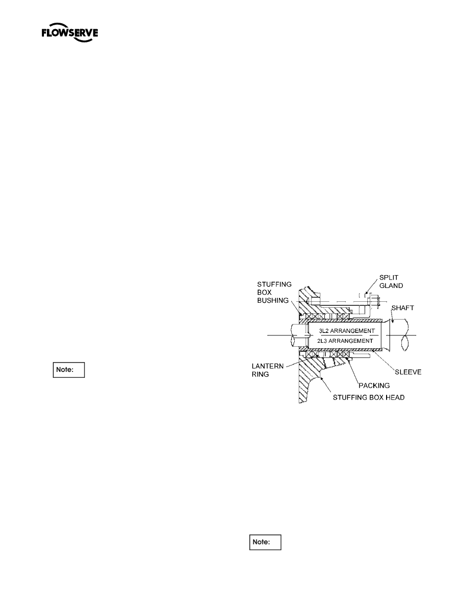
6.10.5.2 Standard Packing
a) Assemble the stuffing box head [4110] over the
shaft sleeve [2445] and orientate the lantern ring
connections to auxiliary piping (Refer to Figure 6).
These connections are normally placed on the
vertical centerline for proper venting and draining as
well as providing optimum gland stud access.
b) Push the stuffing box head [4110] back against the
bearing frame flange face. Back off the thrust
bearing housing to line up with the stuffing box with
shaft sleeve. The shaft sleeve should be lined up
with the stuffing box or fairly proud off the stuffing
box by 0.060” [1.50mm].
c) Install the shaft gasket [4590.3] onto the shaft,
ensuring that the outside diameter is no larger than
the sleeve.
6.10.6 Impeller Installation
a) Install impeller [2200].
b) Apply a small quantity of Loctite 242 or
equivalent to the exposed thread on the end of
the shaft, and thread the impeller nut [2912]
complete with O-ring [4610.2] onto the shaft.
For units with mechanical seals, do not
apply thread locking compound until seal axial
setting has been established.
c) Tighten the impeller nut [2912] in accordance
with the specific Impeller torque specified, see
section 6.6. This is an essential step to properly
seat the sleeve [2445] and compress the gasket
[4590.3] to provide a seal and to prevent
loosening of the impeller on the shaft.
d) Release the thrust bearing housing set screws
[6577] and index the bearing housing [3240] to
move the impeller in or out.
6.10.7 All pumps
a) Smear anti-seize compound on the casing [1112]
and stuffing box head [4110] rabbit fit (spigot)
diameters to ease assembly and future
disassembly.
6.10.8 Rotor unit
a) With a sling around the bearing frame placed so
as to balance the weight, lift the frame/impeller
assembly keeping the shaft horizontal.
b) Install the frame/impeller assembly into the
casing [1112] by guiding the stuffing box head
and bearing frame spigots squarely into the
casing recess. Ensure that the gasket [4590.3]
stays in position. If the fit becomes snug, use 4
equally spaced bolts to draw the assembly into
the casing.
c) Install the casing frame bolts with washers and
tighten in accordance with section 6.6.
d) Using the thrust bearing housing adjustment
feature [Figure 1], move the impeller forward
away from the stuffing box head [4110].
e) Attach the bearing frame support [3134] to the
bearing frame [3130] using the capscrews and
washers. Ensure that thread engagement is at
least 1 diameter. Use Loctite 242 thread sealant.
f) Set the impeller front clearance in accordance
with instruction earlier in this section of the
manual.
6.10.9 Shaft seal
6.10.9.1 Gland packing
Standard Packed Box Arrangement
a)
Insert one packing ring at a time into the stuffing
box. Push the packing as far as possible into the
packing bore.
b)
Install additional rings as required, staggering the
joints.
c)
Once the first two or three rings of packing have
been inserted, the two piece lantern ring [4134]
must be installed. Push the lantern ring and
previously installed packing. The ports in the lantern
ring do not need to be aligned with the inlet/outlet
ports.
d)
Ensure that the shaft can be turned by hand.
e)
Install the remaining rings of packing, alternating
the joints.
It may not be possible to insert the last ring in