3 grouting, 4 initial alignment – Flowserve MPT User Manual
Page 16
MPT USER INSTRUCTIONS ENGLISH 85392699 06-09
Page 16 of 41
®
Low vibration levels and long pump life will be
obtained when the foundations have an adequate
mass. Best practice requires the mass of the
foundation block to be five times the mass of the
equipment.
4.2.3 Install baseplate
Install the baseplate onto packing pieces (approx.
25 mm (0.984 in.) to 50 mm (1.969 in.)) evenly
spaced and adjacent to foundation bolts. Level the
baseplate to within 1 mm (0.039 in.) in every 3000
mm (118.11 in.) using a machinist’s level on the
machined surfaces of the pump and driver pads,
placing shims between baseplate and packing
pieces. The pump and driver have been aligned
before dispatch. Check alignment of pump and
motor half coupling. If this is incorrect, it indicates
that the baseplate has become twisted and should
be corrected by re-shimming.
4.3 Grouting
4.3.1 Grouting foundation bolts
Where applicable, grout in the foundation bolts.
4.3.2 Grouting baseplate
After adding pipe work connections and rechecking
the coupling alignment, the baseplate should then
be grouted in accordance with good engineering
practice. Fabricated steel and cast iron base plates
should be filled with grout. If in any doubt, please
contact your nearest Flowserve service center for
advice.
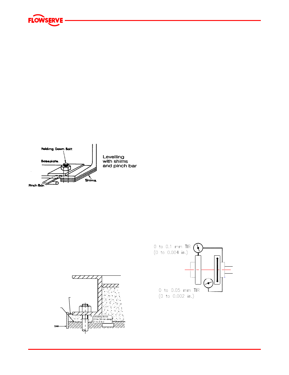
GROUTING TO BE
25 TO 50mm DEEP
FINISHED GROUT
LEAVE TOP OF
FOUNDATION ROUGH.
CONCRETE
DO NOT FINISH
WITH TROWEL
4.3.3 Grouting baseplate prevents movement
Grouting provides solid contact between the pump
unit and foundation, prevents lateral movement of
vibrating equipment, and dampens resonant
vibrations.
4.4 Initial alignment
4.4.1 Thermal expansion
The pump and motor will normally have to be
aligned at ambient temperature and should be
corrected to allow for thermal expansion at
operating temperature. In pump installations
involving high liquid temperatures, the unit should
be run at the actual operating temperature, shut
down, and the alignment checked immediately.
4.4.2 Alignment methods
4.4.2.1 Ensure the pump and motor half
couplings are disconnected.
4.4.2.2 The alignment MUST be checked.
Although the pump will have been aligned at the
factory, it is most likely that this alignment will have
been disturbed during transportation or handling.
Align the motor to the pump, not the pump to the
motor. Alignment is achieved by adding or
removing shims from under the motor feet and also
moving the motor horizontally as required. In some
cases where the alignment cannot be achieved, it
will be necessary to move the pump before
recommencing the above procedure.
4.4.2.3 For couplings with narrow flanges, use a
dial indicator gauge as shown.
The alignment values are maximal for continuous
service.
4.4.2.4 Permissible misalignment limits at
working temperature:
Parallel alignment within 0.1 mm (0.004 in.) TIR
Angular alignment within 0.05 mm (0.002 in.) TIR