Flowserve ISC2 Dual Pusher Repair User Manual
Page 11
11
Figure 28
Figure 29
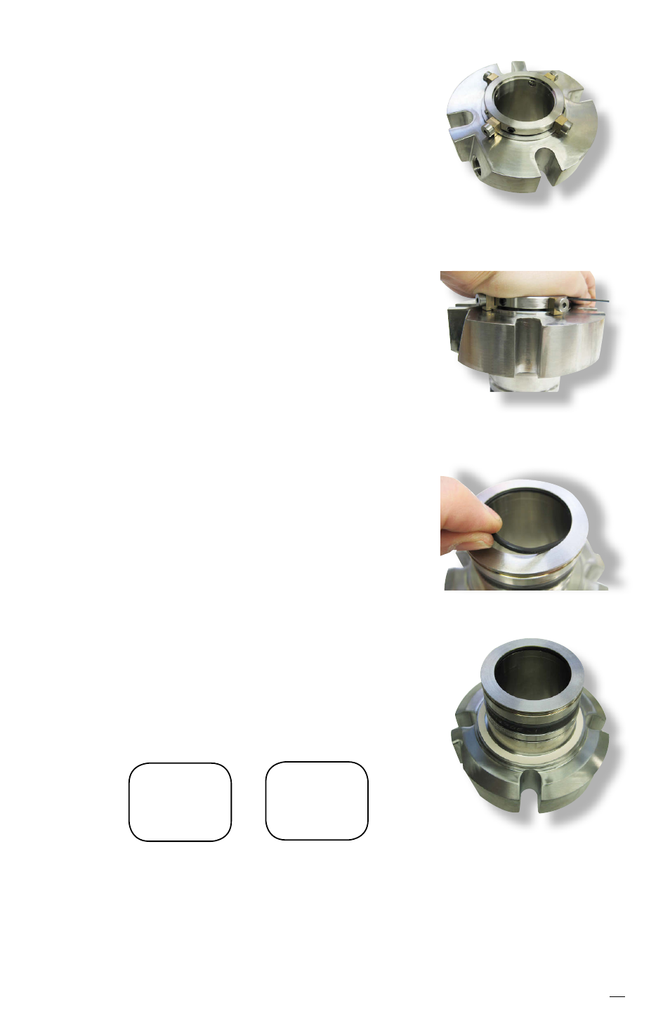
Figure 30
6.23 Install the drive collar [58] onto the sleeve
assembly and rotate carefully until the set screws
and quarter-dog set screws line up with their
respective holes in the sleeve.
6.24 Install setting devices [103] and cap screws [40]
onto the drive collar [58], engaging with the gland
[11]. See Figure 27.
6.25 Compress the collar to be even with the end of
the sleeve assembly. This will also compress
the gland and inner gland simultaneously. While
holding the collar in compression, tighten the
quarter-dog set screws [57.1] into the holes in
the sleeve until snug. If the seal does not contain
quarter-dog set screws then install the set screws
[57] into the sleeve [1]. See Figure 28.
Caution: Over tightening of the quarter-dog
set screws will cause distortion of the sleeve
assembly [1]. Check integrity of the sleeve
with a plug of the appropriate size to ensure
no distortion has occurred.
6.26 Install the sleeve O-ring [19] into the ID groove
of the sleeve assembly. See Figure 29.
6.27 The cartridge seal assembly is now ready for
testing.
6.28 Adhere the gland gasket [18] to the inner gland
gasket surface with a spray adhesive such as
3M Super 77
®
. See Figure 30.
6.29 Permanently mark the seal type ISC2-PP, seal
size and gland ring material clearly on the gland
surface. See Figure 1 for placement location.
ISC2-PP
M060
C-276
Example
inch
marking
ISC2-PP
1.875
316 SS
Example
metric
marking
Figure 27