Plan 54 - forced circulation, Figure 2 – Flowserve MW-200 Series User Manual
Page 6
Advertising
6
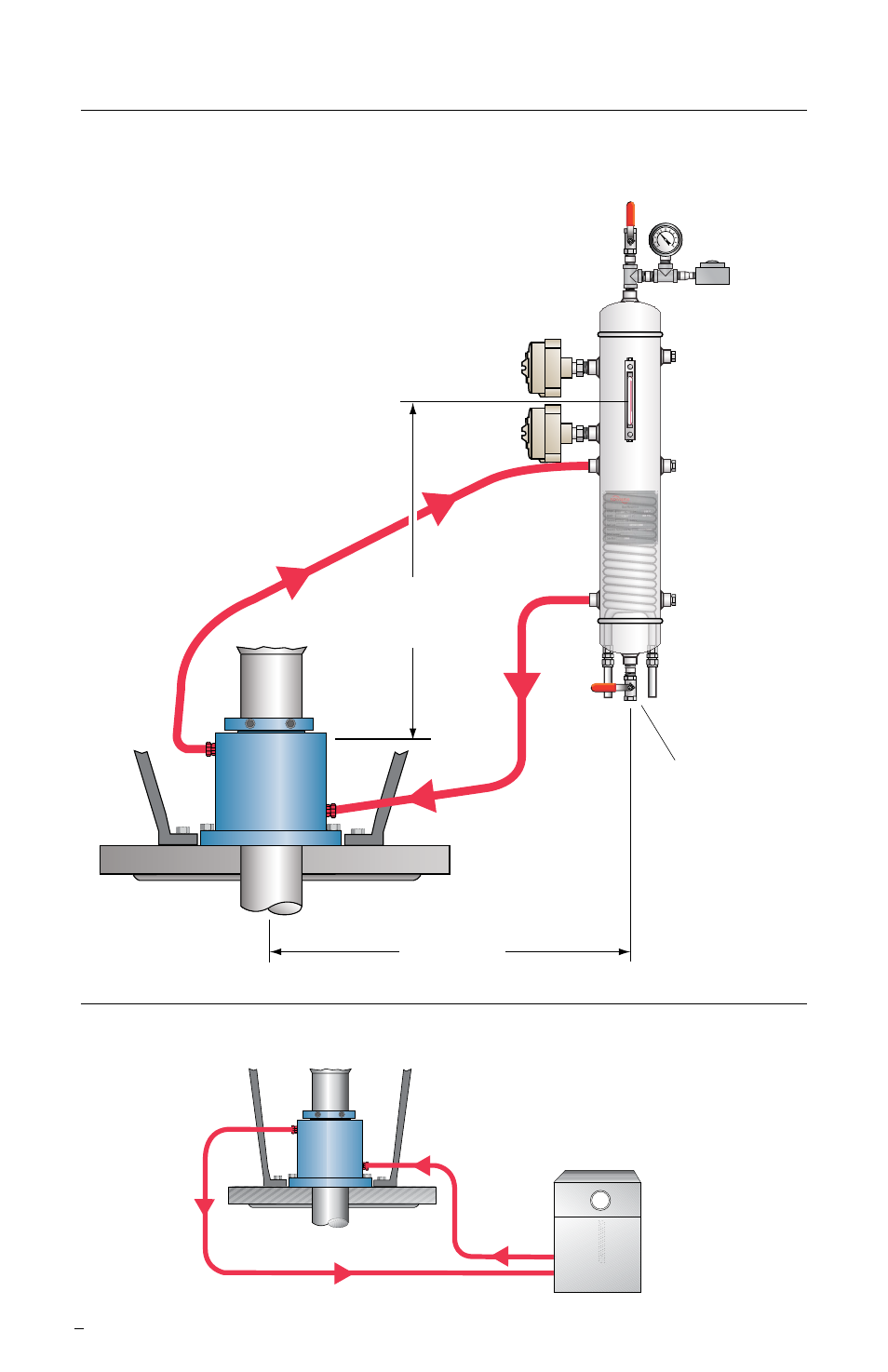
Recommended Piping for Dual Liquid Lubricated Seals
Plan 53A - Induced Circulation (high shaft speeds)
Figure 2
Plan 54 - Forced Circulation
Buffer
Outlet
Buffer Inlet
Circulator
1.2 m (4 ft.)
max
Pressure
Indicator
Pressure
Source
Pressure
Switch
Drain
Seal Support Reservoir
with Cooling Coil Option
Level
Switch
(low)
Level
Switch
(high)
Cooling In
Cooling
Out
Fill Connection
Barrier
Inlet
Barrier
Outlet
0.91 m (3 ft.)
normal liquid
level
Advertising
This manual is related to the following products: