1 equipment check, Seal chamber requirements figure 2 – Flowserve Pac-Seal Type 21 User Manual
Page 3
3
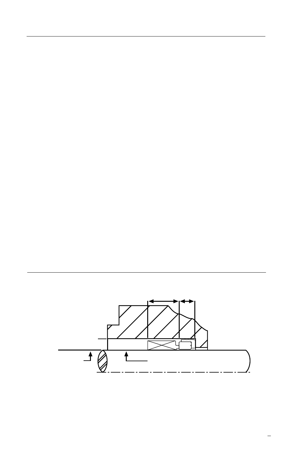
Seal Chamber Requirements
Figure 2
Sleeve or shaft finish to be
1.6 μm (63 μinch) R or better
a
Shaft or sleeve OD
-0.050 mm (-0.002 inch)
• Bearings must be in good condition
• Maximum lateral or axial movement of shaft (end play) = 0.25 mm (0.010 inch) FIM
• Maximum shaft runout at face of seal housing = 0.05 mm (0.002 inch) FIM
• Maximum dynamic shaft deflection at seal housing = 0.05 mm (0.002 inch) FIM
• Verify proper shaft and bore lead in chamfers are present and within specifications.
Difficulty and damage can be observed during seal installation without proper
lead in chamfers.
Seal Chamber Bore
-0.050 mm (-0.002 inch)
Seal Working
Height
Mating
Ring
Width
1 Equipment Check
1.1 Follow plant safety regulations prior to equipment disassembly
including, but not limited to, the following:
• Lock out motor and valves
• Wear designated personal safety equipment
• Relieve any pressure in the system
• Consult plant MSDS files for hazardous material regulations
1.2 Disassemble pump in accordance with equipment manufacturer’s
instructions and remove sealing arrangement.
1.3 Check Seal documentation for seal design and materials of
construction.
1.4 Check shaft or pump sleeve outer diameter (OD), seal working
height, mating ring width, and seal chamber bore to ensure they are
dimensionally within the tolerances shown on the seal assembly
drawing. See Figure 2.