Flowserve ST Series User Manual
Page 3
3
• Bearing, drive, and coupling must be in good condition
• Maximum vertical shaft movement (axial end play) = 0.13 mm (0.005 inch) FIM
• Maximum static vessel flange out of concentricity = 0.13 mm (0.005 inch) FIM
• Maximum dynamic shaft deflection = 0.38 mm (0.015 inch) FIM
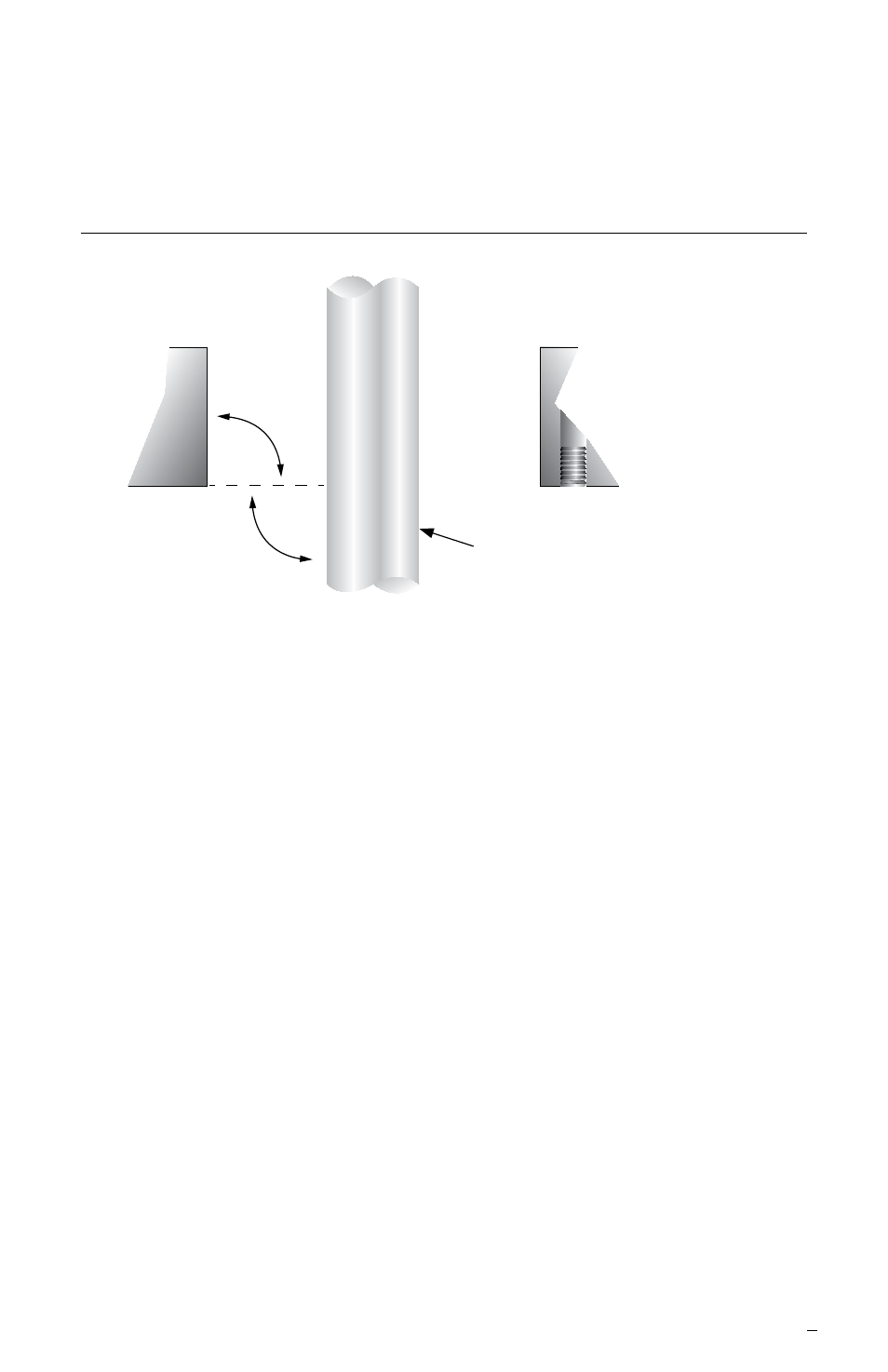
Seal Chamber Requirements
Figure 2
1.6 Check assembly requirements for platform stability. Refer to
Figure 2 for required squareness, concentricity, and surface
finish requirements.
89.9°
to
90.1°
89.9°
to
90.1°
Shaft OD to be ± 0.03 mm
(± 0.001 inch) with a surface finish
of √ 32 μinch (0.8 μm) Ra or better
1.7 Check the assembly drawing accompanying the seal assembly
for specific seal design data, materials of construction, dimensions
and recommended piping connections.
1.8 Check the shaft outside diameter, vessel flange bolt size, bolt
circle, and distance to coupling or drive to ensure that these
dimensions agree with the associated seal assembly drawing.
Pay special attention to the flange bore dimensions for roundness
and concentricity to the shaft.
1.9 Handle the seal assembly with care, it is manufactured to precise
tolerances. These seals are lapped to rigid specifications required
for boundary lubrication. If it becomes nescessary to disassemble
the seals keep these faces clean a all times and protect them from
damage since they are subject to impact fracture.