2xlc bearing installation – Flowserve XLC Series User Manual
Page 3
3
1.7 Check mounting plate bolt holes and bolt circle to ensure they are the
same as shown on the assembly drawing.
1.8 Inspect individual bearing components for any significant notches,
scratches, or dings. The wiper seals, WR600 insert, and spherical sur-
faces of the metallic components should be kept clean and free of debris.
1.9 Handle the XLC bearing with care; it is manufactured to precise toler-
ances. The bearing surfaces are of special importance and should be kept
perfectly clean at all times.
1.10 Tools needed for installation: An open-end wrench and torque wrench
sized for the gland bolt nuts, a flat head screw driver, and hex head
wrenches sized for the bearing housing and carrier cap screws.
2
XLC Bearing Installation
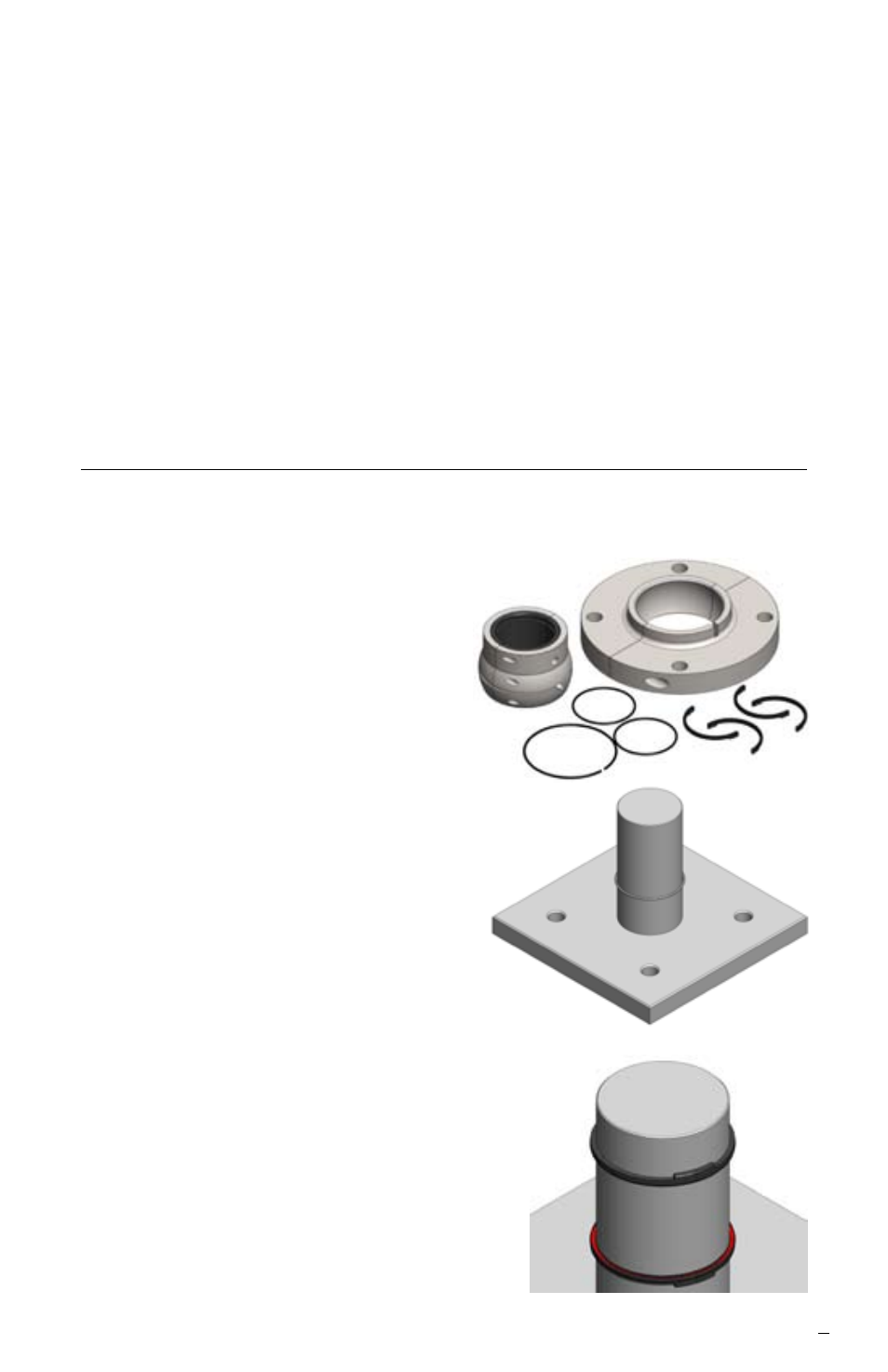
2.1 The XLC bearing will come from the factory partially assembled without
the wiper seals and O-rings installed. Partially disassemble the bearing for
installation.
2.1.1 Unbolt the halves of the
housing and set aside the
cap screws for future use in
assembly.
2.1.2 Unbolt the halves of the
carrier assembly and set
aside the cap screws for
future use in assembly.
2.2 Join one ball and socket O-ring
around the shaft.
2.2.1 Do not attempt to disconnect
the O-ring. This will destroy
the locking feature and make
the O-ring unusable.
2.3 Place upper wiper jacket around
shaft so the anti-rotation tab points
up. Insert ball and socket O-ring into
wiper jacket cavity from below.
2.3.1 Repeat step 2. 2. Place
lower wiper jacket around
shaft so the anti-rotation tab
points down. Insert ball and
socket O-ring into wiper
jacket cavity from above.