Flowserve ISC1BX User Manual
Page 5
Advertising
5
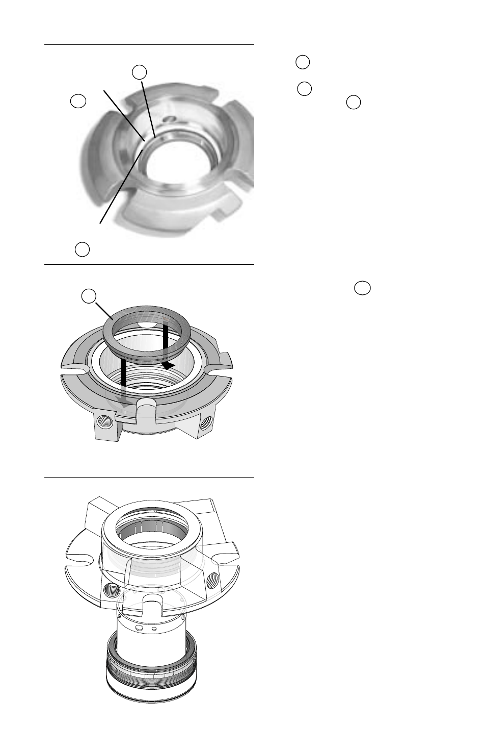
4.6 Place the mating ring O-ring
P
in the gland assembly
behind the gland drive ring
1B
. Place the vibration
dampener
M
into the groove
at the front surface of the
gland drive ring. (
Figure 7
)
4.7 Align the two flats on the
mating ring
3A
with the two
flats on the inside of the
gland drive ring in the gland
assembly, and press the
mating ring in place using
finger pressure only. (
Figure 8
)
4.8 Place the gland/mating ring
assembly face down over the
sleeve/bellows assembly.
(
Figure 9
)
Figure 7
Figure 8
Gland
Drive Ring
1B
Figure 9
Vibration
Dampener
M1
O-ring
P
Mating Ring
3A
Advertising
This manual is related to the following products: