Flowserve ISC1PX User Manual
Page 6
6
4.10 Place the outboard dynamic
seat gasket O-ring
13 in the
dynamic O-ring surface of the
gland assembly. (Figure 10)
4.11 Align the gland assembly
drive pins (Figure 10) with
the slots in the outside
diameter of the stationary
face support. Firmly and
evenly press the gland onto
the stationary face support.
(Figure 11)
Caution: do not rotate the gland
to align pins while
pressing down. This
could damage the
springs. Once the gland
is in the proper position
do not rotate it until the
seal is fully assembled
to ensure that the pins
remain engaged.
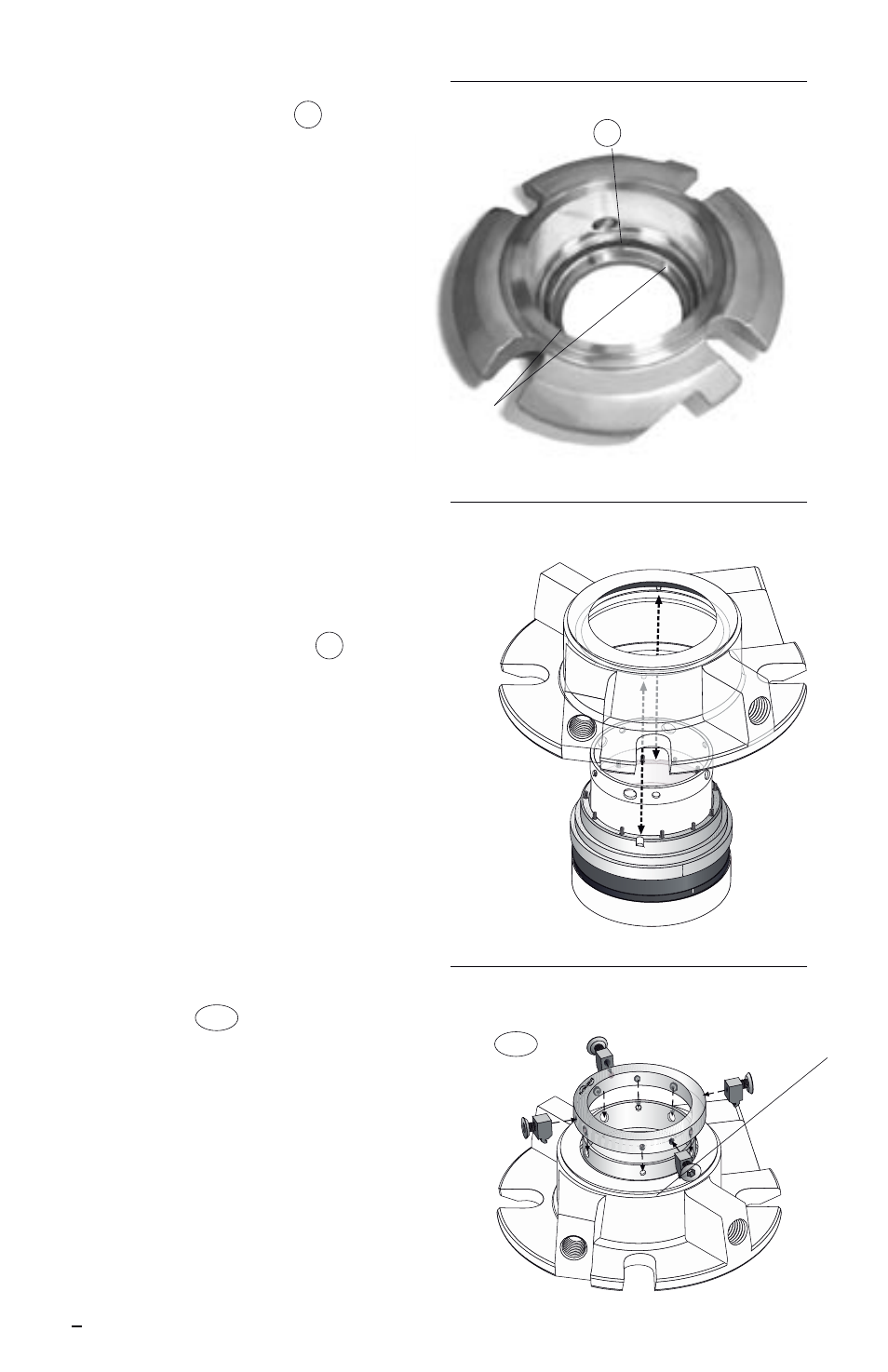
4.12 Place the drive collar
58
onto the end of the sleeve
with the “Flowserve” logo
facing up. (Figure 12) Align
the quarter dog set screws
with the smaller holes in the
end of the sleeve. On smaller
seal sizes, one of the quarter
dog set screws will be offset
by 15 degrees. Align this
quarter dog set screw with
the corresponding offset hole
in the end of the sleeve. Do
not tighten any set screws at
this time. Install the setting
devices
103 and flat head
cap screws into the drive
collar while engaged with the
gland. Be sure to keep the
drive collar aligned and be
careful not to rotate the
gland.
Figure 10
Figure 11
Figure 12
Seat Gasket O-ring
13
Gland
Assembly
Drive Pins
Setting
Devices
103