Installed cartridge seal assembly and plan 23, 3piping instructions – Flowserve D Series User Manual
Page 3
2.5
Orient the ports on the seal gland(s) as indicated by the seal assembly drawing
and connected piping.
2.6
Evenly torque gland bolts/nuts for uniform gland pressure against the seal
chamber. On cartridge seals, do not yet tighten drive collar screws.
2.7
Complete the remaining equipment assembly including bearings, if applicable.
2.8
On cartridge seals, evenly tighten drive collar screws.
2.9
Disengage setting plates from the sleeve and secure in disengaged position.
2.10 Inspect equipment and driver alignment in accordance with coupling and/or
equipment manufacturer’s instructions.
2.11 After bringing the equipment up to operating conditions, recheck alignment and
make adjustments as necessary.
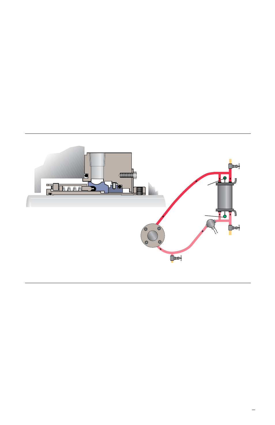
3
Installed Cartridge Seal Assembly and Plan 23
Figure 2
3
Piping Instructions
3.1
Refer to the seal assembly drawing for recommended seal piping plans. D seals
are designed for Plan 23, follow all installation and operating instructions provided
with these systems.
3.2
Minimize restrictions, total tubing length and number of bends especially in closed
loop systems. Unless otherwise specified, the minimum internal diameter for tubing
and connecting hardware should be 19 mm (0.750 inch).
3.3
In Plan 23 loop systems, pipe runs should be sloped continuously for proper
venting and draining, and to promote thermosyphoning in standby condition. Include
a high point vent. Unless otherwise specified, coolers must be mounted 45 – 60 cm
(18 – 24 inches) above and up to 90 cm (36 inches) laterally from the center of the
shaft. Reservoirs follow the same vertical guidelines and are allowed up to 120 cm
(48 inches) lateral distance from the center of the shaft.
3.4
Do not start the equipment dry. Vent the equipment, seal chamber, and all
piping systems then startup support systems before starting equipment.
seal
end view
high point vent,
normally closed
low point drain,
normally closed
cooling
out
cooler
cooling
in
temperature
indicator
outlet
inlet