Flowserve ISC2SS User Manual
Page 9
Advertising
9
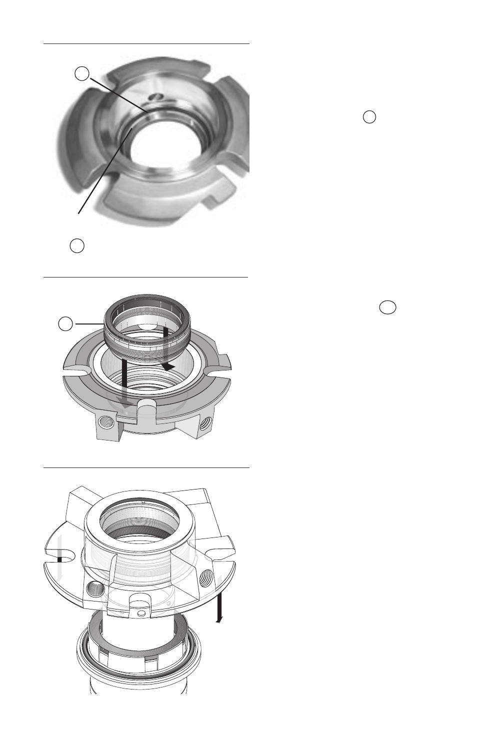
Figure 17
4.15 Place the gland/bellows
assembly face down onto the
sleeve/outboard mating ring
assembly. (
Figure 19
)
Figure 18
4.15 Assemble the outboard
bellows O-ring
P
into the
gland assembly. (
Figure 17
)
Figure 19
4.16 Assemble the outboard
bellows assembly
34
into
the gland assembly, aligning
the drive flats on the gland
assembly and bellows
assembly. (
Figure 18
)
O-ring
P
Gland
Drive Ring
1B
Outboard
Bellows
Assembly
34
Advertising
See also other documents in the category Flowserve Hardware:
- Tandem Seal (8 pages)
- 978 Chemiepac (12 pages)
- ISC2 Single Pusher Repair (8 pages)
- LS-300 Series Durametallic (4 pages)
- Pac-Seal Type 16 (8 pages)
- U Series BW Seals (4 pages)
- ISC2 Dual Pusher Repair (12 pages)
- ISC2 Single metal bellows seal (8 pages)
- Durametallic Double CRO (8 pages)
- VRA-C Series Durametallic (4 pages)
- ISC2 Dual metal bellows sea (12 pages)
- Single Inside Pusher Type Seal (8 pages)
- Bearing Gard (2 pages)
- X-200 (12 pages)
- GTS Series (12 pages)
- MSS Series (12 pages)
- SLC Series Interseal (12 pages)
- QB Series BW Seals (8 pages)
- SLM-6100 (12 pages)
- SLM-6200 (12 pages)
- High Temperature Metal Bellows Seals (8 pages)
- X Series BW Seals (8 pages)
- ML-200 Series Durametallic (8 pages)
- ML-200 Series Durametallic (8 pages)
- Circulator (12 pages)
- ISC Series (16 pages)
- Gas Barrier Control System (4 pages)
- CPM Series (8 pages)
- CPM Series (12 pages)
- Mechanical Seal and Seal Support System Storage (4 pages)
- RIS Seal (12 pages)
- 682 Seal Cooler (8 pages)
- ISC2 Series (8 pages)
- ISC2 Series (116 pages)
- Pac-Seal Type 52 (8 pages)
- Pac-Seal Type 31 (8 pages)
- ST Series (8 pages)
- Mechanical Seal General (16 pages)
- Dual Pressurized Seals (8 pages)
- Uniseal Series BW Seals (8 pages)
- XLC Series (8 pages)
- PSS II Durametallic (8 pages)
- PSS II (16 pages)
- ISC1SX (8 pages)
- ISC1PX (8 pages)