Flowserve Dual Gas Barrier Seals User Manual
Page 10
10
dimensions. It must not be possible to overstress these components, e.g. the
max permitted tightening torque must not be exceeded.
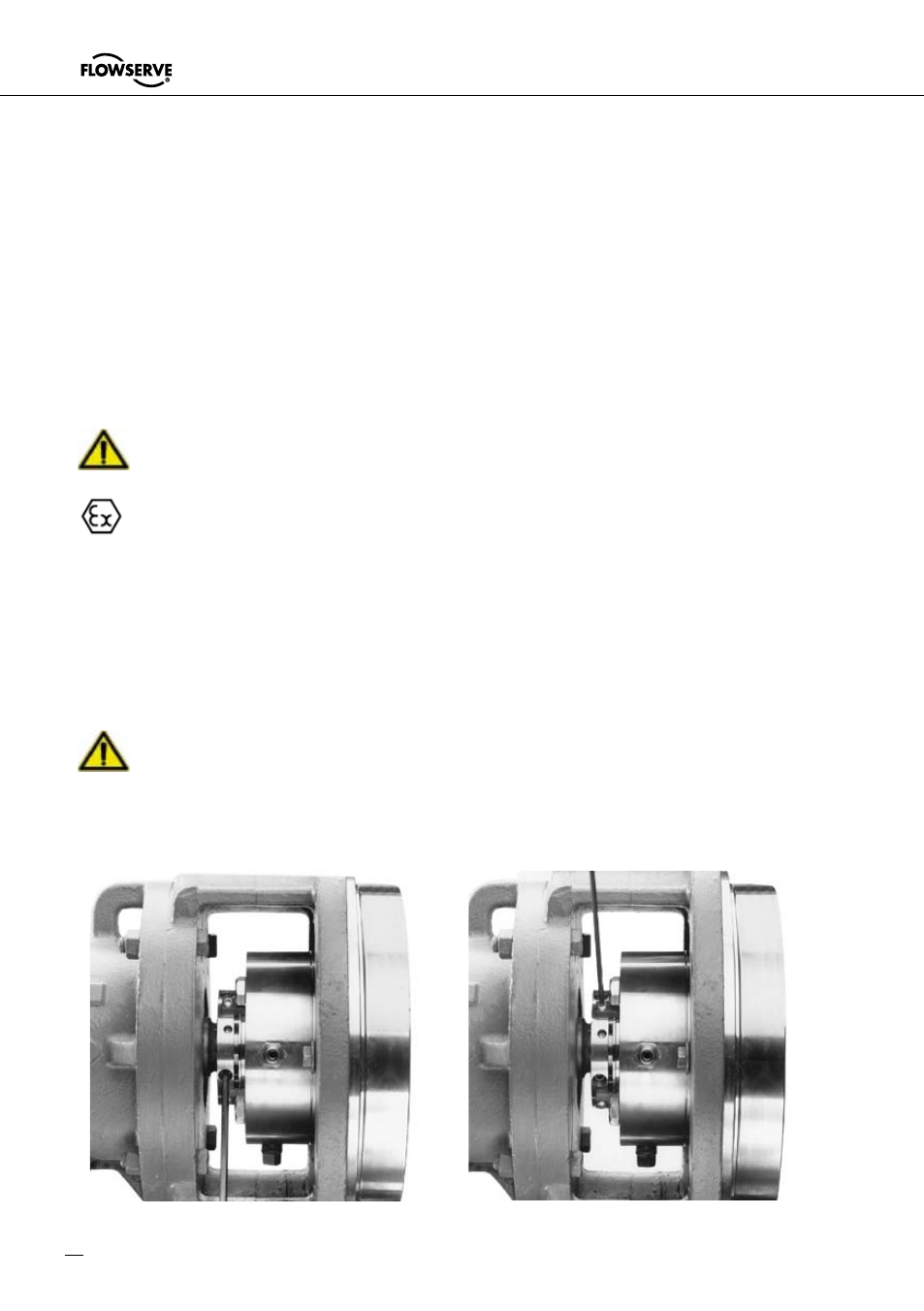
6.6 Using a cross-tightening method tighten the set screws on the seal cartridge
drive collar, Figure 6.
!
Inaccurate tightening of these screws can lead to unsafe situation as mechani-
cal seal may move out of the seal chamber when pressure is applied.
6.7 Remove setting devices by removing the screws with an Allen wrench, Figure
7. Save the setting devices and screws for future use in either removing the
seal from service or to reset the pump impeller, see section 9.
Vibrations must be prevented from transferring to the installed seal during
operation, e.g. through structural measures implemented on the machine.
The machine to take the seal must be earthed in accordance with the applicable
regulations for electrical installations (e.g. VDE rules) to conduct away any
electrostatic build-up and so
prevent spark formation.
6,8 Turn the shaft by hand to ensure free operation.
6,9 Pipe up the gland connections to the seal, see section 7.
6.10 See Functional Recommendations, section 8, before starting pump.
Conduct a static pressure test. Do not exceed the max. pressures.
Remove setting devices
Tighten drive collar set screws
Figure 6
Figure 7