Flowserve X-100 User Manual
Page 5
5
of the gland may be necessary with
some pump designs to permit seal
piping to clear the bearing housing.
Refer to the assembly drawing
that is supplied with the seal for
proper positioning. Bolt the back
plate in place on the bearing
housing.
2.3 Assemble the pump, adjust the
bearings, set the impeller and
connect the coupling so
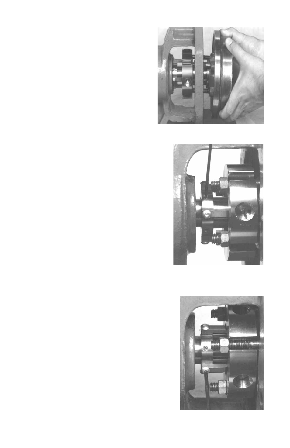
Install pump backplate
Figure 4
Tighten drive collar
set screws
Figure 5
that the shaft is in its operating
axial position. Any subsequent
adjustment of the shaft requires
resetting of the seal. Connect
pump piping, allow no pipe strain
on the pump casing.
2.4 Position the X-100 cartridge gland
with the gland gasket in place against
the seal chamber (stuffing box) face
and
tighten the nuts evenly, cross
staggering the adjustment of the nuts.
The gland nuts should be torqued to
a maximum of 13 N-m (10 ft-lbs).
Excessive gland nut pressure can
result in distortion of the stationary face.
2.5 Tighten the set screws on the X-100
cartridge drive collar with the Allen
wrench provided. See Figure 5.
2.6 Remove setting devices by removing
the cap screws with the Allen wrench
provided. See Figure 6. Save the setting
devices for use if pump impeller must be
reset or if the X-100 is removed for
maintenance.
2.7 Turn the shaft by hand to ensure free
operation.
2.8 Pipe up the gland connections to the
X-100 seal, see section 3.
2.9 See Operational Recommendations,
section 4, before starting pump.
Remove setting devices
Figure 6