Flowserve BX2001 Durco User Manual
Page 24
DURCO BX2001 USER INSTRUCTIONS ENGLISH 9-13
24
(e) Slide the remaining PTFE washer followed by the metal
washer (cup side facing the PTFE washer) over the adjust-
ment stud and thread the two jamb nuts onto the stud.
(f) Finger tighten the jamb nut adjacent to the metal thrust
washer on each side of the thrust plate and check for
acceptable centering of the disc in the valve body by
measuring the gap as explained in Step 12. If the disc is
off center, then adjust the position by turning either nut
to pull or push the disc into position.
(g) Once the disc is centered, simultaneously tighten the two
inside jamb nuts to 40 ft-lbs.
(h) Tighten the outside jamb nuts to 200 ft-lbs. Make certain
that the inside jamb nuts do not turn while tightening the
outside nuts. Check for acceptable disc centering.
(i) Tack weld the adjustment stud to the valve shaft and out-
side jamb nuts to the adjustment stud.
14. Install the seat package following the procedure for
seat replacement in Section IV.
15. If manual operators were removed, re-install them
using the procedures in Section VIII for gears or
Section X for levers.
16. Operate the valves a few times to insure that the valve
disc turns freely into and out of the seat. Seat testing
of repaired valves is recommended.
SECTION VII
COMPLETE VALVE REPAIR (continued)
11. Turn valve over so that the valve body seat pocket is
up and level the disc face to the valve body.
12. Remove the top adjuster and slide the grounding
spring over the shaft. Replace the adjuster and tighten
the adjuster bolts to the torque specifications listed
on page 25 of this manual. For valves that have top
and bottom stem packing, the tightening of adjuster
fasteners can push the disc assembly off-center to the
valve body seat pocket. Alternate fastener tightening
between top and bottom packing to keep disc centered
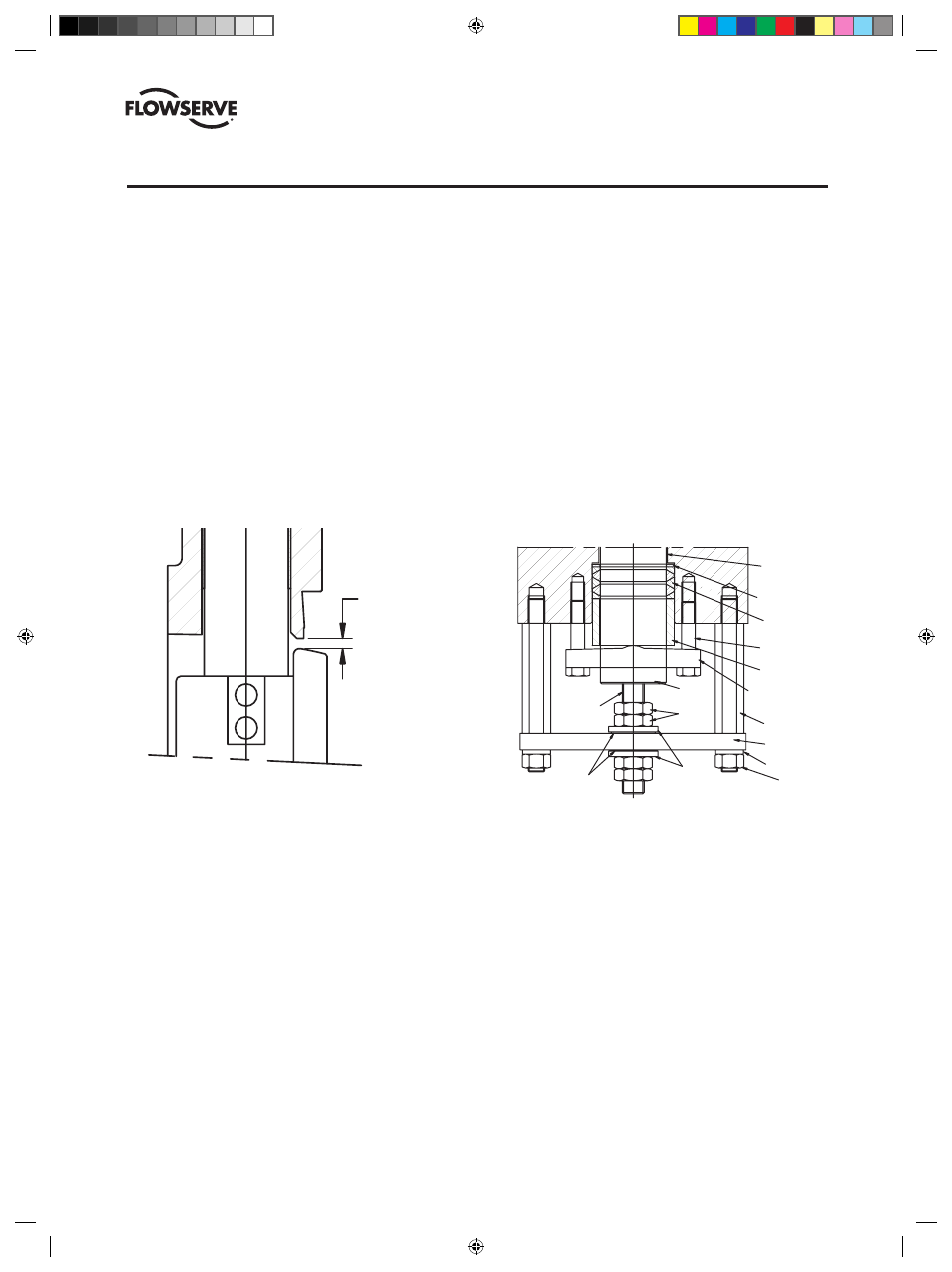
in the valve body. Check the gap between the disc and
the valve body seat pocket. The maximum acceptable
gap difference (measured at the top and bottom of
the disc) is .015". Make certain to identify the style of
packing used in the valve in order to select the proper
fastener torque. Note: Packing styles are illustrated
on page 25.
13. For valves with an external disc support design,
assemble the disc support hardware on the bottom of
the valve body. See Figure 4.
(a) Thread the four support studs into the tapped holes on
the end of the body.
(b) Apply thread cement and thread the ajustment stud into
the shaft until it bottoms in the tapped hole and torque to
100 ft-lbs.
(c) Thread two jamb nuts onto the adjustment stud and slide
one metal thrust washer (cup side away from nuts) and
one PTFE thrust washer over the adjustment stud.
(d) Fasten the thrust plate to the support studs with four lock
washers and nuts.
PACKING
ADJUSTER
PACKING
GLAND
GROUND
SPRING
STEM
PACKING
PACKING
THRUST
WASHER
STEM
BEARINGS
DISC
THRUST
BEARING
DISC
PIN
MEASURE
GAP
HERE
TO CENTER
DISC IN
BODY
GAP
SHOULD
BE
EQUAL
TOP
AND
BOTTOM
SUPPORT STUD
THRUST PLATE
LOCK WASHER
NUT
PACKING ADJUSTER
PACKING GLAND
ADJUSTER BOLT
STEM PACKING
PACKING
THRUST WASHER
SHAFT BEARING
THRUST
WASHER
THRUST
BEARING
JAMB
NUTS
ADJUSTMENT
STUD
SHAFT
FIGURE 4
External Disc Support Design
(DVENIM0390-02)-BX2001_update.indd 24
10/10/13 2:08 PM