Flowserve StarPac 3 User Manual
Page 22
StarPac Intelligent Control System FCD VLENIM0066-05 04/14
22
®
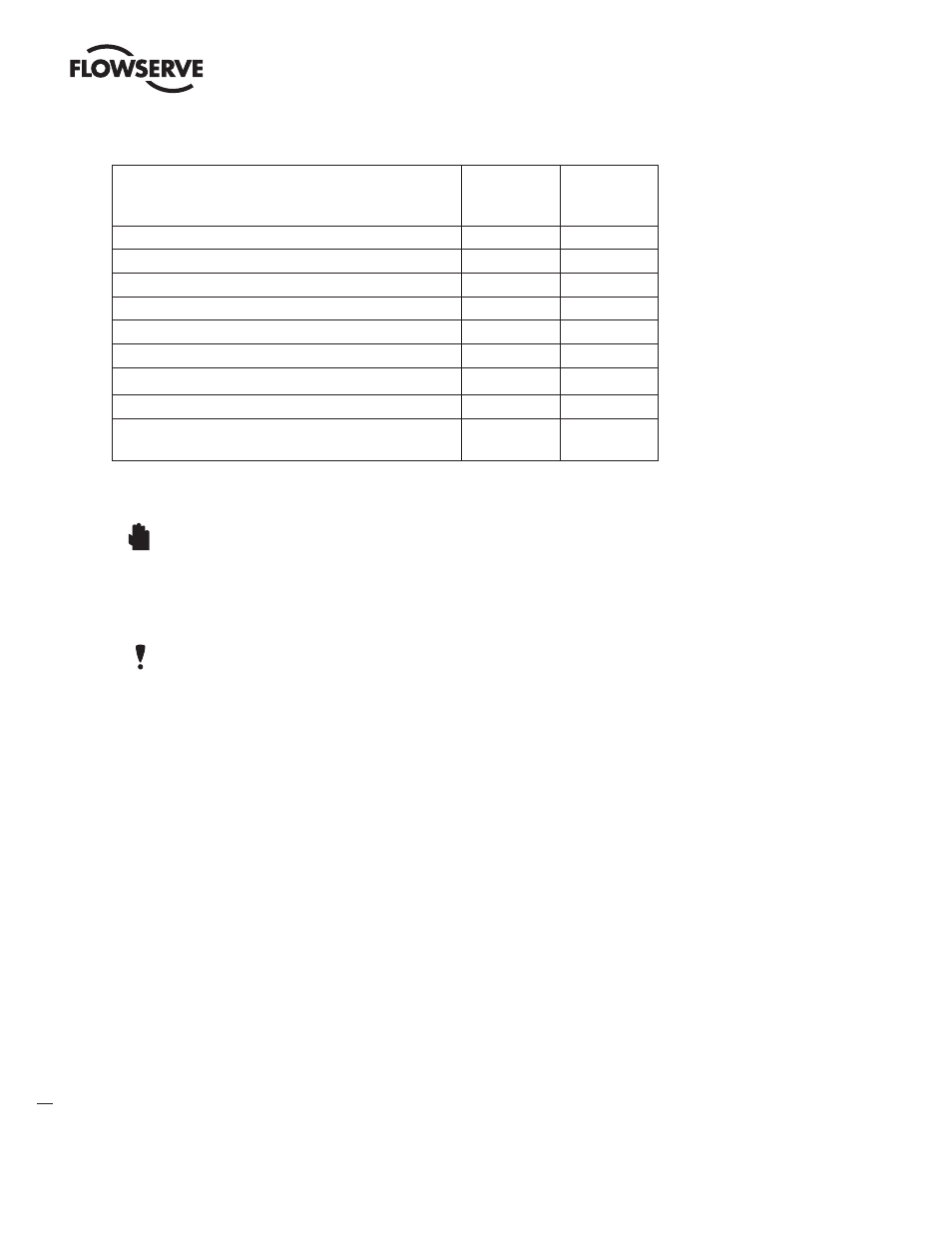
Table IX: User Interface Terminal Connections
Signal
Positive
Terminal
Number
Negative
Terminal
Number
24 VDC power
1
10
Primary RS-485 communication link
2
11
Secondary RS-485 communication link
3
12
Valve command signal
4
13
Auxiliary input (4-20 mA)
5
14
Analog output (4-20 mA) 1
6
15
Analog output (4-20 mA) 2
7
16
Discrete output (pulse or alarm relay)
8
17
Discrete input - switch/ solenoid monitoring (discrete
mode source input)
9
18
1. Remove the customer interface cover.
WARNING: Do not remove the electronic housing covers in flammable atmospheres; otherwise, possible
injury to personnel or equipment may occur.
2. Connect the required wires to the terminal interface block and computer as described in Figure 6 and Table IX.
(The system must have 24 VDC power for operation).
NOTE: The StarPac 3 unit remembers the operating mode setting (automatic or manual) from the last time
the unit had power. When power to the system is turned on again, the unit will resume operation in the previ-
ous mode. Normally the unit arrives from the factory set in the manual analog operating mode. This means
a command signal will position the valve the same as a traditional control valve, providing a plug position
proportional to the 4 - 20 mA signal.
3. To avoid upsetting the process because of improper operating mode selection:
Ensure that the system arrived from factory with the proper operating mode setting in the shop prior to in-
stallation by connecting air supply and command signal, then turning on the power and looking at the mode
value on the local display, or;
Set the proper operating mode for the particular application in the shop prior to installation by selecting the
desired operating mode from the local interface or in the Tuning/Tune screen of the StarTalk XP Or StarTalk
DTM software, or;
Ensure that the block valves in the process line around the unit are closed and the process is diverted around
the unit.
4. Turn on the 24 VDC power to the unit, and verify that it has been correctly wired by checking the following:
• 24 VDC power is at least 150 mA and between 18.0 and 36.0 VDC
• Polarity is correct
• Local display is on; if not, check the power supply
After the verification is completed, replace the main and user interface covers on the housing.
STOP!